background image

RAID Subsystem DVA-16K | Installation Manual

Subsystem Connection and Operation | en

 35


Bosch Security System

F.01U.027.799 | V2 | 2008.08

5.2

Host Connection Topology 

There is no direct association between host ports and drive channels. Drives are associated 

with host port IDs as the logical configuration of drives, e.g., a logical drive. A logical drive can 

be composed of drives on different drive channels, and a logical drive can be associated with 

target IDs on different host ports. 

Drive access contention (that may happen when two (2) host computers can access the same 

array) and data-path failover activities should be handled by a third-party software running on 

host computer(s).

RAID subsystem host channel SCSI connectors are connected to the servers via host bus 

adapters (HBAs) that have been installed on the host computer(s). 

Single server connection: If a single logical drive is mapped to a single server, a RAID 

management software should be installed in the server to execute RAID functionality.

Multiple server connection: If a single logical drive is mapped to two (2) separate servers 

through dual-redundant data paths, separately purchased, third-party multipathing and 

clustering software must be installed on both servers. The clustering software will ensure 

that if one (1) server or the data path to a single server fails, the second server will con-

tinue to provide access to the data.

5.2.1

Single Host

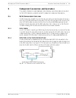
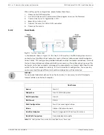
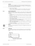
In the example shown in 

Figure 5.2

, one of the SCSI ports on the controller rear panel is con-

nected to a single host computer.

Fig. 5.2

Single Host Connection

Single Server

Servers

One (1)

Subsystem

One (1) subsystem

RAID Controllers

One (1)

RAID Level

RAID 5

Disk Configuration

One (1) or more logical drives

Drives

Sixteen (16) drive channels

Host Bus Adapters

One (1) single-port SCSI

Data Path Connection

Dual-redundant data paths

Table 5.1

Configuration Overview for Single Server Connection

Summary of Contents for DVA-16K SCSI

Page 1: ...RAID Subsystem DVA 16K DVA 16K SCSI Premium Series en Installation Manual ...

Page 2: ......

Page 3: ... 1 LCD Panel 13 2 5 2 Drive Trays 13 2 5 3 The RAID Controller Module 14 2 5 4 Controller Module Interfaces 14 2 5 5 DIMM Module 15 2 5 6 Battery Backup Unit BBU 15 2 5 7 Power Supply Units 15 2 5 8 Cooling Modules 16 2 6 Subsystem Monitoring 17 2 6 1 I2C bus 17 2 6 2 LED Indicators 17 2 6 3 Firmware FW and Bosch RAIDWatch GUI 17 2 6 4 Audible Alarms 17 2 7 Hot swappable Components 18 2 7 1 Hot sw...

Page 4: ...38 5 3 2 Daisy Chain Procedures 38 5 4 Power On 39 5 4 1 Check List 39 5 4 2 Power On Procedure 39 5 4 3 Power On Status Check 40 5 4 4 LCD Screen 40 5 5 Power Off Procedure 41 6 Subsystem Maintenance 42 6 1 Overview 42 6 1 1 About Subsystem Maintenance 42 6 1 2 General Notes on Component Replacement 42 6 2 Replacing Controller Module Components 43 6 2 1 Controller Module Maintenance Overview 43 6...

Page 5: ...ifications 61 7 4 Power Supply Specifications 61 7 5 Cooling Module Specifications 62 7 6 RAID Management 62 7 7 Fault Tolerance Management 63 8 Appendix Spare Parts and Accessories 64 8 1 Spare Parts 64 8 2 Accessories 64 9 Appendix Pin Outs 65 9 1 VHDCI SCSI Port Pin Outs 65 9 2 DB9 Audio Jack Pin Outs 66 9 3 DB9 Audio Jack UPS Cable Pin Outs 67 9 4 Null Modem 67 9 5 Ethernet Port Pin Outs 68 9 ...

Page 6: ...Handle subsystem modules using the retention screws eject levers and the metal frames face plates Avoid touching PCB boards and connector pins To comply with safety emission or thermal requirements none of the covers or replace able modules should be removed Make sure that all enclosure modules and covers are securely in place during operation Be sure that the rack cabinet into which the subsystem...

Page 7: ...vision reception which can be determined by turning the equipment off and on you are encouraged to try to correct the interference by one or more of the following measures Reorient or relocate the receiving antenna Increase the separation between the equipment and receiver Connect the equipment into an outlet on a circuit different from that to which the receiver is connected Consult the dealer or...

Page 8: ... enhanced 3U RAID storage subsystem chassis is a 3U metal chassis divided into front and rear sections which are respectively accessed through front and rear panels Pre drilled mounting holes in the sides of the 3U RAID subsystem enclosure allow you to attach sepa rately purchased slide rails so that you can install the enclosure into a rack or cabinet The modular design of the active components f...

Page 9: ...re or the Bosch RAIDWatch web based GUI The firmware can be accessed by using either the LCD panel see Figure 2 2 located at the front of the subsystem or a terminal emulation program installed on an external computer and connected to the COM1 on the controller module s rear panel see Figure 2 2 with the provided serial cable Fig 2 2 Controller Module Rear Panel If web based management is desired ...

Page 10: ...g Host ID mapping is flexible in the sense that the same array can be associated with different host ID LUNs allowing the host clustering configurations Drives on different channels can then be grouped into an array and the array has its unique volume size stripe size and opti mization mode Arrays of different RAID levels can be striped together into logical volumes making management of huge volum...

Page 11: ... easily insert extract the chassis into from a rack or cabinet The LCD panel on the left handle provides an easy way for you to monitor and configure your subsystem The front panel of the RAID subsystem described in this manual is shown in Figure 2 4 A description of each front panel component is given below Fig 2 4 RAID subsystem Front View The front panel shown in Figure 2 4 accommodates the fol...

Page 12: ... RAID controller module A controller board and a DDR RAM DIMM module are housed in the controller module to provide the system RAID functionalities See Section 2 5 3 The RAID Controller Module BBU A BBU sustains cache memory during a power shortage to prevent data loss See Section 2 5 6 Battery Backup Unit BBU PSUs The hot swappable PSUs provide power to the subsystem A power switch is located on ...

Page 13: ...nitial screen will show the subsystem model name A different name may be assigned for the system or differ ent arrays This will enable easier identification in a topology with numerous arrays 2 5 2 Drive Trays Fig 2 8 Drive Tray Front View The RAID subsystem comes with sixteen 16 drive trays See Figure 2 8 designed to accom modate separately purchased standard 1 inch pitch 3 5 inch disk drives The...

Page 14: ...sible location on the controller board for easy insertion of the DDR RAM DIMM module 2 5 4 Controller Module Interfaces All external interfaces that connect to external devices are located on the controller module rear panel shown in Figure 2 9 The interfaces are listed below Fig 2 9 Controller Module Interfaces Host Ports Two 2 SCSI 320 host channels CH0 and CH1 in Figure 2 9 connect the subsyste...

Page 15: ...and the fifth LED on the rear panel of the controller module will flash slowly See Section 4 2 6 BBU Module LED for details on the LED indicators You can check the sta tus of the battery s charge via Bosch RAIDWatch or the firmware 2 5 7 Power Supply Units The RAID subsystem is equipped with two 2 redundant hot swappable 460W PSUs which are located at the rear of the enclosure See Figure 2 6 The P...

Page 16: ...slots located in the lower section of the PSU modules see Figure 2 12 The two 2 9 7cm fans housed in each cooling module pro vide two 2 fan speeds When the subsystem is running in normal ambient temperature the fans operate at the lower speed When the temperature reaches the temperature threshold the fans automatically change to high speed to generate more cooling air from the front to the rear of...

Page 17: ...a Scan Media Scan handles low quality drives in both the degraded mode and during the rebuild pro cess Maintenance tasks will then be performed on an entire array or specific hard drives Var ious options are user configurable such as priority start time and execution internals Bosch RAIDWatch Bosch RAIDWatch is a premier web based graphics user interface GUI that can be installed on a remote compu...

Page 18: ...e subsystem when they are being replaced At no other time should these components be removed from the subsystem 2 7 2 Components The following components are hot swappable Power supply units PSUs Cooling modules BBU Hard drives 2 7 3 Normalized Airflow Proper subsystem cooling is referred to as normalized airflow Normalized airflow ensures the sufficient cooling of the subsystem and is only attain...

Page 19: ...g the RAID subsystem you should first check to see that you have received all the required components See Section 3 5 Unpacking the Sub system If any items appear damaged contact your vendor for a replacement 3 Hard drives Up to sixteen 16 SATA I or SATA II hard drives must be purchased sepa rately prior to the RAID subsystem installation 4 Cabling The RAID subsystem requires an external VHDCI to ...

Page 20: ...the module s metal frame face plate only Avoid touching the PCB boards and connector pins 6 None of the covers or replaceable modules should be removed in order to maintain com pliance with safety emission or thermal requirements 7 Always secure every enclosure module by its retaining screws or make sure it is held in place by its latches 8 Always make sure the subsystem has a safe electrical eart...

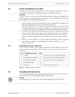
Page 21: ...r or an external device 5 Power up Once the components have been properly installed and all cables are properly connected you can power up the subsystem and configure the RAID array See Section 5 4 Power On 3 4 1 Installation Procedure Flowchart Table 3 1 shows a flowchart of the installation procedure As you complete each step check the Done box on the right Please use this flowchart in conjuncti...

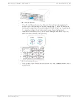
Page 22: ... hard drives have been installed in the drive trays the drive trays can be installed into the RAID subsystem 1 Make sure the key lock is in the unlocked position i e the groove on its face is in a hori zontal orientation If the groove is in a vertical position as shown in Figure 3 1 then the key lock is locked and the front flap on the drive tray cannot be opened Fig 3 1 Front View of an Individua...

Page 23: ...f the drive tray is firmly connected to the corresponding connector on the mid plane board If the front flap is not closed properly the connection between the hard drive and the subsystem will not be secure 5 Lock the flap into place by turning the key lock until the groove on its face is pointing down vertical orientation See Figure 3 4 Fig 3 4 Drive Tray Key lock Rotation 6 Once the drive tray i...

Page 24: ...ient is a powerful module that runs as a back ground Disk and Executive Monitor DAEMON independent from Bosch RAIDWatch that can be installed redundantly on different hosts It is used for event notification via email fax LAN broadcast SNMP traps MSN Messenger ICQ SMS short messages and the configuration utility screen The Configuration Client helps prevent blind time and keeps you constantly infor...

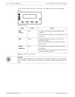
Page 25: ... the ENT button for two 2 seconds on the initial screen to enter the Main Menu Press the ESC button to clear the current event Press the UP and DOWN arrow keys to select viewing items In the last item View and Edit Event Logs the most recent event is displayed first For dual RAID controllers the LCD shows the status of the primary controller Press the UP and DOWN arrow keys for more than one 1 sec...

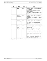
Page 26: ...ied to the subsystem BUSY White FLASHING indicates that there is activity on the host drive channels OFF indicates that there is no actively on the host drive channels ATTEN Attention Red ON indicates that a component failure status event has occurred OFF indicates that the subsystem and all its compo nents are operating correctly Table 4 2 LCD Panel LED Definitions i NOTICE During the power up pr...

Page 27: ...l array Fig 4 2 Drive Tray LEDs 4 2 4 Controller Module LEDs The rear panel of the controller module is shown in Figure 4 3 The LEDs on the controller s faceplate that can be accessed from the rear of the enclosure are numbered from 1 to 5 The definitions are shown in Table 4 4 Fig 4 3 LEDs on the Controller Module Name Color Status Drive Busy Blue FLASHING indicates data is being written to or re...

Page 28: ...ivity on the host ports 3 Drv Bsy Drive Busy Green FLASHING indicates there is activity on the drive ports OFF indicates there is no activity on the drive ports 4 C_Dirty Cache Dirty Amber ON indicates that the cache memory is dirty or is being held up via the BBU during a sys tem power loss 5 BBU Fail Amber ON indicates the BBU cannot sustain the cache memory This maybe caused by a missing BBU OF...

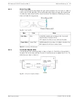
Page 29: ...ar panel See Figure 4 5 The function is the same as the fifth LED on the controller module The LED is off when the BBU is functioning normally and is able to sustain the cache memory The LED flashes to indicate the BBU is charging If the LED is illuminating amber please re charge the BBU or contact your system vendor to verify the problem Fig 4 5 BBU Module LED 4 2 7 PSU LEDs Each PSU comes with a...

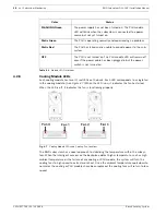
Page 30: ...erature such as high ambient temperature or the failure of any cooling or PSU module the system will turn the cooling fans to high speed to extract more heat Once the ambient temperature cools down to normal or the cooling or PSU modules have been replaced the cooling fans will return to low speed Color Status FLASHING Green The power supply has not been turned on The PSU module LED will blink whe...

Page 31: ...4 7 shows the default threshold values for the RAID subsystem If any of these values are surpassed the alarm will sound The thresholds in Table 4 7 are default threshold values and may be changed 4 3 2 Failed Devices If any of the following devices fail the audible alarm will be triggered RAID controller module Cooling modules PSU modules BBU Hard drives CAUTION If an alarm is triggered it is nece...

Page 32: ...1U 027 799 V2 2008 08 Bosch Security System 4 4 Monitoring Presence detection and the general working status of the cooling fan and other modules are monitored through an I2C serial bus If any of these modules fail you will be notified via the various methods described above ...

Page 33: ...s the Ultra 160 standard allowing users to store data at the fastest SCSI speeds available 5 1 1 SCSI Cables One 1 SCSI cable is used for each RAID subsystem for host connection A second SCSI cable is used to connect the second host channel Use only high quality SCSI 320 cables from a rep utable manufacturer To ensure optimum performance it is necessary to use proper high quality durable SCSI 320 ...

Page 34: ...e in the daisy chain configuration the terminator will be automatically disabled Although it is not recommended if you prefer to disable the firmware setting for the on board terminator using the LCD keypad panel on the subsystem RS232C terminal session or Bosch RAIDWatch management software the auto detection function is also disabled Typically the host computer or host adapter SCSI card inside t...

Page 35: ...ection If a single logical drive is mapped to a single server a RAID management software should be installed in the server to execute RAID functionality Multiple server connection If a single logical drive is mapped to two 2 separate servers through dual redundant data paths separately purchased third party multipathing and clustering software must be installed on both servers The clustering softw...

Page 36: ...ides both path and host computer redundancy If one of the host channels becomes disconnected for some reason or the cable connecting one of the host ports to the host computer is damaged the second path can transmit data from the sub system to the host computer Similarly in the clustered hosts configuration the same array can be accessed through different data paths and downtime will be minimized ...

Page 37: ...p the configurations please follow these steps 1 Power on the RAID subsystem 2 Use the LCD panel or the terminal emulation program to access the firmware 3 Create at least one 1 or two 2 logical drives LD0 and LD1 4 Map all the LD to CH0 and CH1 5 Connect the server1 to CH0 CH1 connector 6 Connect the server2 to connector 7 Power on the servers ...

Page 38: ...o the SCSI IN port on the back of the RAID subsystem 2 Daisy chain subsystems If you wish to connect more than one subsystem an extra VHDCI to VHDCI SCSI cable is required Attach one end of the cable to the SCSI OUT port and the other end to the SCSI IN port in the next subsystem 3 Assign chassis IDs Each chassis must be assigned a unique chassis ID before being pow ered on The chassis ID for the ...

Page 39: ...sys tem and plugged into the main power source Ambient temperature All the subsystem components have been acclimated to the sur rounding temperature 5 4 2 Power On Procedure When powering on the RAID subsystem please follow these steps 1 Power on the subsystems that are not connected directly to the host computer if applied If you have daisy chained any RAID subsystem power on those subsystems bef...

Page 40: ...ied to the system 4 Firmware and Bosch RAIDWatch The overall status of the system may be checked using the pre installed firmware or the Bosch RAIDWatch GUI 5 Audible alarm If any errors occur during the initialization process the onboard alarm will sound in a hastily repeated manner 6 Drive tray LEDs should start flashing indicating that the RAID control units are attempt ing to access the hard d...

Page 41: ...o flush all cached data This prepares the RAID subsystem to be powered down 3 Turn off the power Turn off the power switches at the top of the rear panel Once the subsystem has been powered down other devices that are connected to the subsystem may be powered down Initializing Please Wait This screen appears when the PSUs are turned on DVA 16K Modem Not Config This screen appears after the initial...

Page 42: ... familiar with the RAID subsystem should be the only ones who make component replacements If you are not familiar with the RAID subsystem or with RAID subsystem maintenance in general it is strongly advised that you refer RAID subsystem maintenance to a suitably qualified maintenance technician Normalized airflow depends upon the presence of all subsystem components A subsys tem component even if ...

Page 43: ...rmanent damage to the controller board resulting in lengthy delays for the end user Prior to replacing the controller module it is imperative for your own safety to be sure that no power is being supplied to the system 6 2 2 Removing the Controller Module To remove the controller module 1 Make sure there is no data access to the subsystem to avoid losing any data Use the soft ware provided on the ...

Page 44: ...er module making sure that the memory module is securely in place See Section 6 3 DIMM Module Replacement 3 Install the controller module Make sure the levers at the back of the controller module are down Align the controller module with the controller module bay at the rear of the subsystem Gently slide the controller module in See Section 6 3 Installing the Controller Module Fig 6 3 Installing t...

Page 45: ...ig 6 5 Installing the Controller Module Screws 6 Re attach all the cables that were removed These include the cables that connect to the host and the expansion chassis any Ethernet cable that was previously attached to the LAN port and any cables that were attached to the COM ports 7 The system is now ready to power up ...

Page 46: ...RAID subsystem supports DDR RAM DIMM mod ules with memory capacities between 256MB and 1GB Installation considerations When installing the DDR RAM DIMM module it is necessary to remove the controller module The controller board is more susceptible to damage than the other components and must be handled with extreme care Secure installation When replacing the DIMM module make sure that the new DIMM...

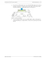
Page 47: ...h the slot and gently but firmly push it in The white clips on either side of the slot should automati cally close and lock the new DIMM module into place See Figure 6 7 Fig 6 7 Installing the DIMM Module 4 Install the controller module Once the new DIMM module has been installed place the controller module back in its original location See Section 6 2 3 Replacing the Controller Module ...

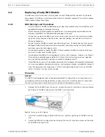
Page 48: ... or modify the BBU If disassembled the BBU could leak acid over heat emit smoke burst and or ignite Do not pierce the BBU with a sharp object strike it with a hammer step on it or throw it These actions could damage or deform it internal short circuiting can occur possibly causing functional defects acid leak and other hazardous results If the BBU leaks gives off a bad odor generates heat becomes ...

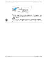
Page 49: ...U is correctly installed into the subsystem the LED should start flashing to indicate that BBU is being charged When the BBU is fully charged the LED will light amber constantly i NOTICE The life expectancy of a BBU is approximately 500 cycles Follow the procedures above to replace an old BBU with a new BBU in order to maintain fault tolerant subsystem functional ities ...

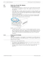
Page 50: ...ixing a PSU of previous series See Figure 6 10 Fig 6 10 Label on the PSU Handle Immediate replacement When a PSU fails it should be replaced immediately However do not remove the PSU module unless a replacement is readily available Removing a PSU without a replacement will cause severe disruptions to the internal airflow and the sub system will overheat possibly causing irreparable damage to some ...

Page 51: ...essing Down the PSU Handle 5 After the PSU module has been dislodged from the enclosure use the handle to gently pull the PSU module out of the enclosure See Figure 6 14 Fig 6 14 Dislodging the PSU 6 Remove the cooling module from the lower level of the PSU module Please refer to Section 6 6 Cooling Module Maintenance Power Socket Power Socket Power Switch Power Switch PSU Handle PSU Handle CAUTIO...

Page 52: ...s down position so that the saddle notches on the lower edges of the handle can lock on to the edge metal brackets along the chassis inner walls Push the PSU into the slot and pull the handle upward to secure the module See Figure 6 16 Fig 6 15 Installing the new PSU Module 9 Secure the PSU to the subsystem by inserting the retention screw to the PSU See Figure 6 16 Fig 6 16 Fastening the PSU Rete...

Page 53: ...f the cooling modules fails it must be replaced as soon as possible The cooling mod ules are secured to the chassis with the two 2 black latches located on the rear surface of the module itself To replace the cooling module please follow these steps 1 To remove the cooling module pull both side latches toward the center of the cooling module Withdraw the cooling module from the subsystem by gently...

Page 54: ...54 en Subsystem Maintenance RAID Subsystem DVA 16K Installation Manual F 01U 027 799 V2 2008 08 Bosch Security System Fig 6 18 Installing the new Cooling Module ...

Page 55: ...pened the drive tray must be removed from the subsystem Failure to remove the drive tray from the subsystem after the flap has been opened may cause data errors Remove drives slowly When removing a drive tray from the RAID subsystem pull the drive tray out only about one inch and then wait for at least 30 seconds for the hard drive motor to spin down before taking it out completely Any impact to t...

Page 56: ... 6 20 Drive Tray Key lock Rotation 3 Open the front flap by pushing the button at the front of the drive tray See Figure 6 21 The drive tray front flap will automatically be lifted and the drive tray will be dislodged from the chassis Fig 6 21 Front View of an Individual Drive Tray 4 Remove the drive tray with the hard drive gently and carefully withdrawing the drive tray with hard drive from the ...

Page 57: ...RAID Subsystem DVA 16K Installation Manual Subsystem Maintenance en 57 Bosch Security System F 01U 027 799 V2 2008 08 Fig 6 22 Removing the SATA Hard Drive 6 Install the new hard drive ...

Page 58: ...ure Operating 0º to 40ºC Non operating 20º to 60ºC Altitude Operating 0 12 000 ft Packaging 0 20 000 ft Power Requirements Input Voltage 100VAC 10A 240VAC 5A with PFC auto switching Frequency 47 63Hz Power Consumption 460W Dimensions Height With handle 131mm Without handle 130mm Width With handle 482 6mm Without handle 445mm Length With handle 504 3mm Without handle 488 2mm Weight Net weight 28 5 ...

Page 59: ...ents UL60950 CB Shock Half sine Operating 10G peak 11ms duration Non operating 100G 180 in sec 240G 2ms half sine Square 240G 2ms half sine Vibration Operating 5 500Hz 0 2G X Y Z Non operating 5 500Hz 1 0G X Y Z Warning Alarms Audible alarms System LEDs Event notification via the Bosch RAIDWatch Manager LCD screen or RS 232C termi nal ...

Page 60: ... channels of SATA II Drive Channels All drive channels are pre set and cannot be changed Cache Mode Write through or write back Cache Memory Up to 1GB DDR RAM DIMM memory with without ECC Number of LUNs Up to 32 per SCSI ID Multiple Target IDs Host Channel Yes Aliases for Target IDs Yes Firmware on Flash Memory Yes Drive Hot swapping Yes CPU 600MHz PowerPC 750FX SCSI Controllers LSI 1030 T DIMM Sl...

Page 61: ... Voltage 100VAC 10A 240VAC 5A with PFC Power Factor Correction Yes Hold up Time At least 16ms at 115 230VAC full load after a loss of AC input I2 C Through backplane to controller Over temperature Protec tion Lost cooling or excessive ambient temperature Cooling Fans Two fans for each unit inside PSU Temperature Operating 0 C to 50 C 32 F to 122 F Storage 40 C to 70 C 40 F to 158 F Humidity Operat...

Page 62: ...S 232C through the included serial cable LCD keypad panel The Bosch RAIDWatch Manager program using in band or Ethernet connection Performance Monitoring Yes Remote Control and Moni toring Yes Event Broadcast Alert Yes via Java based Bosch RAIDWatch Manager and Event Monitor Event Notification Yes via the Bosch RAIDWatch Configuration Client sub module Hardware Connection In band over SCSI Fiber o...

Page 63: ... Battery Back up Option Yes Automatic Drive Failure Detection Yes Automatic Rebuild on Spare Drives Yes Regenerate Logical Drive Parity Yes Bad Block Reassignment Yes Automatic Rebuild upon Failed Drive Replace ment Yes Manual Clone of Suspected Failed Drive Yes Concurrent Rebuild on Multiple Drives in a RAID 0 1 Logical Drive Yes Salvage the 2nd Temporary Failed Drive in a RAID 1 3 or 5 Logical D...

Page 64: ...KK 16A Power supply module enhanced 16 bay subsystem 460W capacity DVA SFAK 16A Cooling fan module for enhanced 16 bay subsystem DVA SCDK 16A SCSI to SATA RAID controller module 2 SCSI 320 host channels 16 SATA II drive channels enhanced 3U enclosure 2 dual stacked VHDCI connectors 256MB DDR memory included Table 8 1 Spare Parts Model Name Description DVA SBBK 00A Battery cell pack Li Ion enhanced...

Page 65: ...6 SD13 3 SD14 37 SD14 4 SD15 38 SD15 5 SDP1 39 SDP1 6 SD0 40 SD0 7 SD1 41 SD1 8 SD2 42 SD2 9 SD3 43 SD3 10 SD4 44 SD4 11 SD5 45 SD5 12 SD6 46 SD6 13 SD7 47 SD7 14 SDP0 48 SDP0 15 GND 49 GND 16 DIFSENS 50 GND 17 TPWR 51 TPWR 18 TPWR 52 TPWR 19 NC 53 NC 20 GND 54 GND 21 SATN 55 SATN 22 GND 56 GND 23 SBSY 57 SBSY 24 SACK 58 SACK 25 SRST 59 SRST 26 SMSG 60 SMSG 27 SSEL 61 SSEL 28 SC_D 62 SC_D 29 SREQ ...

Page 66: ...le is able to connect the COM1 serial port on the controller module rear panel for ter minal emulation management Fig 9 1 RS 232C Audio Jack Pin Outs CN1 Pin Number Pin Name 1 Ground 2 TXD 3 RXD CN2 Pin Number Pin Name 1 NC 2 RXD 3 TXD 4 DTR Shorted 5 GND 6 DSR Shorted 7 RTS Shorted 8 CTS Shorted 9 NC Table 9 2 RS 232C Audio Jack Pin Out Definitions ...

Page 67: ...is cable to connect the COM2 serial port to UPS Fig 9 2 RS 232C Audio Jack Pin Outs 9 4 Null Modem CN1 Pin Number Pin Name 1 Ground 2 TXD 3 RXD CN2 Pin Number Pin Name 1 TXD 2 RXD 3 NA 4 NA 5 NA 6 NA 7 NA 8 NA 9 Ground Table 9 3 RS 232C Audio Jack Pin Out Definitions Swap pin 2 and pin 3 Swap pin 4 and pin 6 Swap pin 7 and pin 8 Table 9 4 Null Modem Pin Outs ...

Page 68: ... Manual F 01U 027 799 V2 2008 08 Bosch Security System 9 5 Ethernet Port Pin Outs Fig 9 3 LAN Port Pin Outs 9 6 Main Power IEC type receptacle Pin Pin Name Pin Pin Name 1 LAN_TXP 5 N2 2 LAN_TXN 6 LAN_RXN 3 LAN_RXP 7 N1 4 N2 8 N1 Table 9 5 Ethernet Port Pin Outs ...

Page 69: ...rive trays 25 dummy plate 12 E easily accessible button 13 electrical earth connection 20 electrostatic discharge 19 ESD damage 20 Ethernet port 24 29 event notification 17 F failover software 36 39 fan failure 15 fan speed 16 faulty module 20 firmware 17 24 front flap 22 23 55 front panel 11 13 G groove 22 GUI 17 H handles 55 hard drive 19 39 42 55 56 host channel 14 host connection 33 35 host re...

Page 70: ... 13 retention screws 20 right handle 11 RJ 45 29 S safety precautions 20 43 SATA drives 55 SATA II drives 55 SCSI cable 33 SCSI 320 8 Self monitoring 24 sensors 30 single host 35 startup 41 static electricity 20 static free 19 subsystem maintenance 42 T thermal notice 20 threshold values 31 transfer rates 33 V ventilation 20 VHDCI SCSI connector 14 ...

Page 71: ......
Page 72: ...Bosch Security System Robert Koch Straße 100 D 85521 Ottobrunn Germany Telefon 49 89 6290 0 Fax 49 89 6290 1020 www bosch securitysystems com Bosch Security System 2008 ...
Reviews: