RAID Subsystem DVA-08K | Installation Manual
Subsystem Monitoring | en
25
Bosch Security Systems
F.01U.027.797 | V1 | 2006.05
4.2.3
Controller Module LEDs
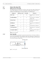
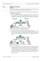
The rear-facing faceplate of the RAID controller module is shown in
. The rear-facing
faceplates on the two models look identical. The LEDs are numbered from 1 to 5. There are
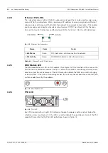
two more LEDs on the Ethernet port. The definitions are shown in
below.
Fig. 4.2
Controller Faceplate
LED Name
Color
Status
Drive Busy
Blue
ON indicates read/write activity on the drive.
OFF indicates there is no read/write activity on the drive.
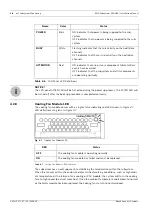
Power Status
Red/
Green
GREEN indicates that power is being supplied to the drive.
OFF indicates no power is being supplied to the drive or the
drive tray is not properly installed. .
RED indicates drive failure or faults have occurred.
Table 4.2
Drive Tray LED Definitions
LED
Name
Color
Status
1
Controller Ready
Green
ON: Indicates controller is active and
operating normally.
FLASHING: Indicates controller initial-
ization is taking place.
OFF: Controller is not ready for opera-
tion.
2
Hst_Bsy
(Host Ports Busy)
Green
FLASHING: Activities on the host ports.
OFF: No activities on the host ports.
3
Drv_Bsy
(Drive Busy)
Green
FLASHING: Activities on the drive side.
OFF: No activities on the drive side.
4
C_Dirty
(Cache Dirty)
Amber
ON: Indicates that data is currently
being cached in memory or is being
held up by the BBU during a system
power loss.
5
BBU_Fail
Amber
ON: Indicates the BBU has failed and
cannot sustain cached data.
OFF: Indicates the BBU can sustain
cached data in memory.
FLASHING: The BBU is charging.
Table 4.3
Controller Module LED Definitions
Summary of Contents for DVA-08K
Page 1: ...RAID Subsystem DVA 08K DVA 08K SCSI Premium Series en Installation Manual ...
Page 2: ......
Page 61: ......

