Installation
Notice!
Use proper surge suppression on cables that are routed outdoors, or close to large inductive
loads or electrical mains supply cables.
!
Caution!
Installation should only be performed by qualified service personnel in accordance with the
National Electrical Code (NEC 800 CEC Section 60) or applicable local codes.
To get the unit operational, perform the following quick install steps:
1.
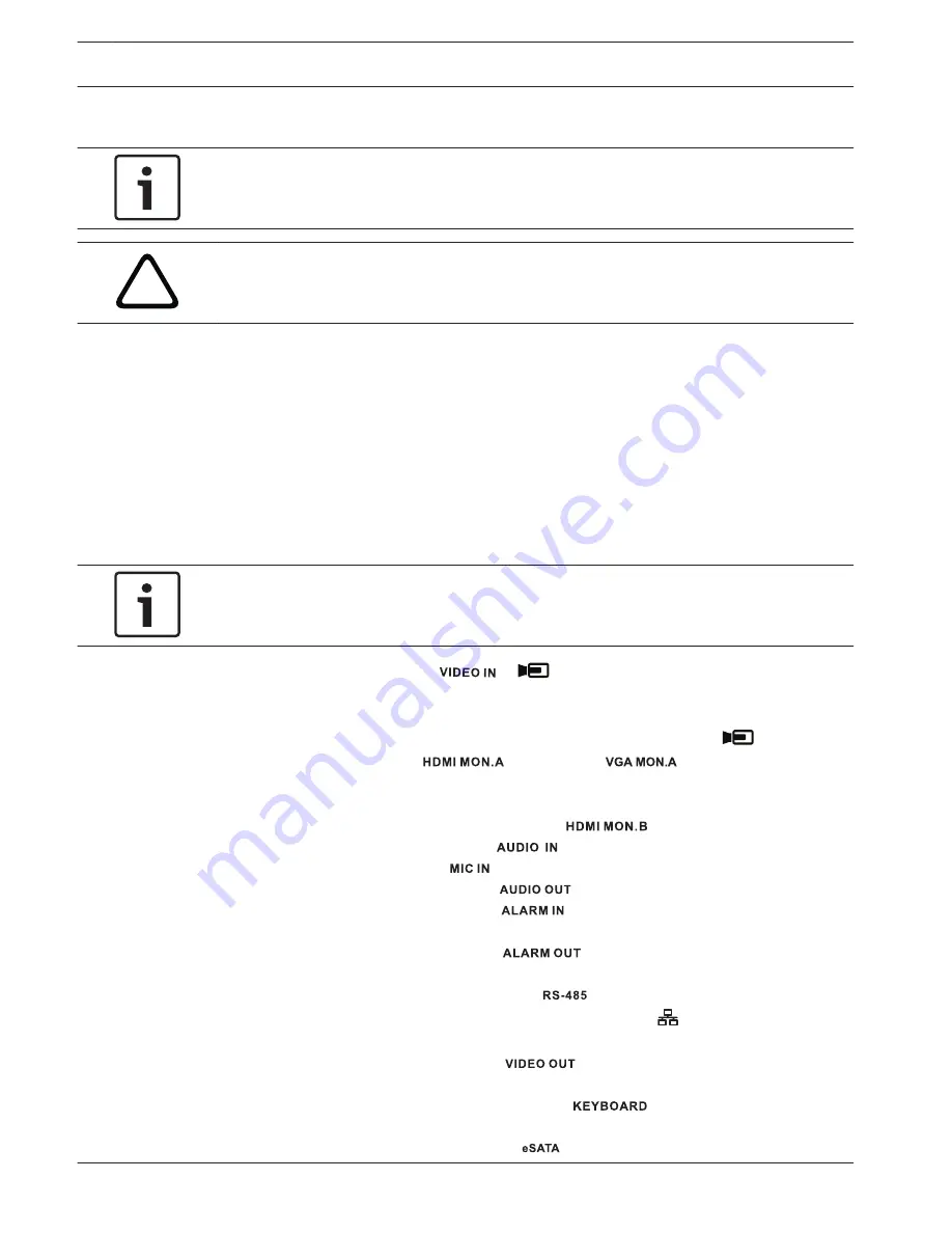
Make all required hardware connections – see Make Connections.
2.
Power up the system – see Powering Up.
3.
Log in – see Login.
4.
Correctly configure your system software with the Startup wizard (this appears the first
time the unit is started) – see Startup Wizard.
After completing this initial setup, the system is ready to run and will show a live view of the
camera image(s). If required, you can alter the settings later using the menus and/or factory
defaults, or you can run the Startup wizard again.
Make connections
Notice!
Use only PoE approved devices.
1.
Connect the cameras to the
or
connectors.
–
If using PoE connector, power is supplied to the camera via the Ethernet cable
compliant with the Power-over-Ethernet standard.
–
Use an external switch to connect more cameras to a single RJ45
port.
2.
Connect monitor A to the
output, or the
output.
3.
Connect the USB mouse to a USB port (back or front panel).
Optional connections (depending on model)
1.
Connect a second dual monitor to the optional
connector.
2.
Connect up to 4 audio signals to the
RCA (CINCH) inputs.
3.
Connect 1 microphone to the
RCA (CINCH) input.
4.
Connect 1 RCA (CINCH) output from
to the monitor or an audio amplifier.
5.
Connect up to 16 alarm inputs to the
connector (via the supplied terminal
blocks).
6.
Connect up to 6 alarm outputs to the
connector (via the supplied terminal
blocks).
7.
Connect a pan/tilt/zoom control unit to the
(only for hybrid models).
8.
Connect to your network via the RJ45 ETHERNET connector
(use Shielded Twisted
Pair Category 5e cable).
9.
Connect extra video out cables to the
ports if loop through is required to other
devices (only for DIVAR 5000 hybrid).
10. Connect a Bosch Intuikey keyboard cable to the
connector using the supplied
adaptor (only for DIVAR 5000).
11. Connect an eSATA storage device to the
connector (only for DIVAR 5000).
5
5.1
8
en | Safety
DIVAR 2000 / DIVAR 3000 / DIVAR
5000
2016.08 | v1.0 | AM18-Q0712
Installation Manual
Bosch Security Systems
Summary of Contents for DIVAR 2000
Page 1: ...DIVAR 2000 DIVAR 3000 DIVAR 5000 Network Hybrid Video Recorder en Installation Manual ...
Page 2: ......
Page 21: ......


