background image

68

en | Advanced configuration menu

Divar XF

F.01U.135.429 | 2.5 | 2009.08

Installation manual

Bosch Security Systems

Check 

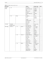
Allow local log on

 to enable local access (always enabled).

Check 

Allow remote log on

 to enable remote access.

Check 

Auto log off

 to enable automatic log off after 3 minutes of inactivity.

6.10.3

User 1 - 7

Up to seven users can be defined with the seven tabs.

Enter  a 

User name

, up to 16 characters.

Enter  a 

Password

 up to 12 characters.

Set different user rights by checking the various check boxes.

In  the 

Control Rights

 tab, set the rights for camera viewing, camera control, camera pre-

positioning, and relay control.

6.11

System

6.11.1

Service

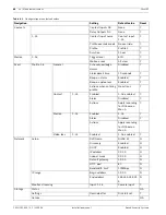
Select 

Restore factory defaults

 to reset the settings in the menu system to their default 

value.

Export diagnostic data

 archives a system info file to a USB memory device when 

connected. This is for service purposes only.

Export system configuration

 saves a copy of the system settings to a USB memory 

device.

Export log for exporting

 saves a log file to a USB memory device containing a list of 

video exports.

Import system configuration

 will load previously saved system settings from a USB 

memory device.

Erase log book

 will delete the contents of the log book.

6.11.2

Serial ports

KBD 

KBD is used to: 

set a unique ID number between 1 and 16 if multiple Divar XF units are controlled with 

one keyboard.

set a first camera number to create a multi-Divar system (for example, Divar 1 has 

cameras 1 - 16; Divar 2 has cameras 17 - 32).

set access rights for each keyboard if multiple keyboards are used with a keyboard 

expander to control a Divar XF.

COM port

The COM port is used for service or integration purposes. 

6.11.3

Licenses

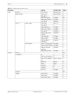
Some optional features require a software license to be obtained before they are activated.

MAC address

 displays the MAC address of the DVR. The MAC address, together with a 

valid license number, is required to obtain an activation key via:

https://activation.boschsecurity.com

The license number and instructions on how to obtain the activation key can be found in 

the letter that is provided when purchasing a Divar XF license.

Installed keys lists all license keys already installed on the system.

Click 

Install key 

to enter a new license activation key.

Available features lists all installed optional features.

Summary of Contents for DHR-1600A-150A

Page 1: ...Divar XF Digital Hybrid Recorder en Installation manual ...

Page 2: ......

Page 3: ...llation environment 15 2 3 1 Mounting 15 2 3 2 Ventilation 15 2 3 3 Temperature 15 2 3 4 Power Supply 15 2 4 Associated equipment 15 3 Quick install 17 3 1 Connections 17 3 1 1 Primary connections 17 3 1 2 Optional connections 17 3 1 3 Powering up 17 3 2 First time use 18 3 3 Quick install menu 18 3 3 1 International 18 3 3 2 Schedule 19 3 3 3 Recording 20 3 3 4 Network 21 4 Hardware setup 23 4 1 ...

Page 4: ...2 Monitor B 38 5 3 3 Viewing 38 5 4 Live and playback 40 5 4 1 Live mode 40 5 4 2 Accessing playback functions 40 5 4 3 Playback mode 40 5 5 Overview of the menu system 41 5 5 1 Access using the front panel keys 42 5 5 2 Access using the mouse 42 5 5 3 Access using the Intuikey keyboard 42 5 6 Search 42 5 6 1 Date time search 43 5 6 2 Event search 43 5 7 Export 45 5 8 Configuration 46 5 8 1 Monito...

Page 5: ...6 7 1 General 63 6 7 2 Contact 64 6 7 3 Motion 64 6 7 4 Video loss 64 6 7 5 Copy 65 6 8 Network 65 6 8 1 Setup 65 6 8 2 IP Range 66 6 8 3 Monitor Streaming 66 6 9 Storage 67 6 9 1 Status 67 6 9 2 Settings 67 6 9 3 Service 67 6 10 Users 67 6 10 1 General 67 6 10 2 Administrator 67 6 10 3 User 1 7 68 6 11 System 68 6 11 1 Service 68 6 11 2 Serial ports 68 6 11 3 Licenses 68 6 11 4 Logging 69 7 Using...

Page 6: ...p button 75 7 3 6 Logout button 75 7 4 Using the control buttons 75 8 Menu default values 77 8 1 Quick install menu defaults 77 8 2 Monitor view settings defaults 78 8 3 Configuration menu defaults 78 9 Technical specifications 83 9 1 Electrical 83 9 1 1 Mechanical 85 9 1 2 Environmental 85 9 1 3 Electromagnetic and Safety 85 9 1 4 Accessories Optional 85 9 1 5 Video bitrates bps 86 ...

Page 7: ... unit Do not place objects filled with liquids such as vases or cups on the unit 6 Lightning For added protection during a lightning storm or when leaving this unit unattended and unused for long periods unplug the unit from the wall outlet and disconnect the cable system This will prevent damage to the unit from lightning and power line surges 7 Controls adjustment Adjust only those controls spec...

Page 8: ...ny change or modification of the equipment not expressly approved by Bosch could void the warrantee or in the case of an authorization agreement authority to operate the equipment 1 2 Safety precautions 1 3 Important Notices All pole power switch Incorporate an all pole power switch with a contact separation of at least 3 mm in each pole into the electrical installation of the building If it is ne...

Page 9: ... unit has been designed to respect the environment as much as possible Electrostatic sensitive device Use proper CMOS MOS FET handling precautions to avoid electrostatic discharge NOTE Wear required grounded wrist straps and observe proper ESD safety precautions when handling the electrostatic sensitive printed circuit boards Fuse rating For security protection of the device the branch circuit pro...

Page 10: ...peration of the equipment is not compromised Mechanical loading Mounting of the equipment in the rack should be such that a hazardous condition is not achieved due to uneven mechanical loading Circuit Overloading Consideration should be given to the connection of the equipment to the supply circuit and the effect that overloading of the circuits might have on overcurrent protection and supply wiri...

Page 11: ... résidentielle Cet appareil génère utilise et émet de l énergie de radiofréquences et peut en cas d installation ou d utilisation non conforme aux instructions engendrer des interférences nuisibles au niveau des radiocommunications Toutefois rien ne garantit l absence d interférences dans une installation particulière Il est possible de déterminer la production d interférences en mettant l apparei...

Page 12: ...re likely to be registered trademarks and must be treated accordingly NOTE This manual has been compiled with great care and the information it contains has been thoroughly verified The text was complete and correct at the time of printing The ongoing development of the products may mean that the content of the user guide can change without notice Bosch Security Systems accepts no liability for da...

Page 13: ...so provided Monitor A displays full screen or multiscreen digital pictures that can be frozen and zoomed Monitor B displays live full screen or multiscreen pictures Use the Control Center PC application via a network for live viewing playback and configuration Five simultaneous users can control multiple Divar XFs The Divar XF includes an authenticity check for both local and remote playback A ded...

Page 14: ...n to exit help 2 2 Unpacking Check the package for visible damage If any items appear to have been damaged in shipment notify the shipping company Unpack carefully This is electronic equipment and should be handled with care to prevent damage to the unit Do not attempt to use the unit if any components are damaged If any items are missing notify your customer service representative or Bosch Securi...

Page 15: ...2 3 4 Power Supply Ensure that the site s AC power supply is stable and within the rated voltage of the unit If the site s AC power is likely to have spikes or power dips use power line conditioning or an uninterrupted power supply UPS 2 4 Associated equipment A typical system could contain the following components not included with the unit A primary monitor for multiscreen monitoring monitor A A...

Page 16: ...16 en Introduction Divar XF F 01U 135 429 2 5 2009 08 Installation manual Bosch Security Systems ...

Page 17: ...in D type connector board 9 Connect the malfunction output via the supplied screw terminal adapter 10 Connect an Intuikey keyboard to the KBD In socket and connect the terminator supplied with the keyboard to the KBD Out socket 11 Connect a Bosch pan tilt zoom control unit to the Biphase port via the supplied 15 pole D type connector board 12 Connect a third party pan tilt zoom control unit to the...

Page 18: ...or A 3 Click Configuration and then Quick install Navigating Use the supplied USB mouse Alternatively use the following front panel keys Use the enter button to select a submenu or item Use the arrow buttons to move through a menu or list Use the escape button to go back or to switch off the menu 3 3 Quick install menu The Quick install menu contains four tabs International Schedule Recording and ...

Page 19: ...ellow Profile 1 Dark blue Profile 2 Green Profile 3 Pink Profile 4 Light blue Profile 5 Brown Profile 6 Click Overwrite to start making changes Select at which day the week should start and end Language Select the language for the menu from the list Time zone Select a time zone from the list Time format Select either a 12 or a 24 hour clock format Time Fill in the current time Date format Select f...

Page 20: ...updated when settings are changed Click Next to move to the next tab 3 3 3 Recording Figure 3 4 Quick install menu Recording Set the Normal recording Resolution Quality and Frame rate for each profile in the table Set the Alarm and Motion recording Resolution Quality and Frame rate These settings are set for all profiles If advanced settings were previously made click Overwrite to replace them wit...

Page 21: ...twork DHCP Enable DHCP to have IP address subnet mask and default gateway assigned automatically by the network server The actual values are displayed IP address Subnet mask Default gateway DNS server Fill in the IP subnet mask default gateway and DNS server addresses when DHCP is disabled Bandwidth limit Restrict the network bandwidth by entering a value between 0 1 and 100 Mbps for the bandwidth...

Page 22: ...22 en Quick install Divar XF F 01U 135 429 2 5 2009 08 Installation manual Bosch Security Systems ...

Page 23: ...l the two supplied silver side covers by 1 inserting them on each side 2 sliding them towards the front of the unit Figure 4 1 Side cover installation 4 2 Rack mounting The unit can be mounted in a 19 inch rack A rack mounting kit is supplied with the unit that includes two rack mounting brackets Mounting 1 Remove the four cross head screws two on each side located near the front panel on the righ...

Page 24: ...the front panel to the right until it is free 3 Place the front panel on top of the unit taking care not to strain the flat cable If there is no room on top of the unit disconnect the flat cable and set the front panel aside CAUTION When installing the assembly into the rack be careful not to restrict air flow around the vents located on the side panels or to exceed the recommended operating tempe...

Page 25: ...the bay with four screws two per side refer to the hard disk documentation 4 Align and slide the bay back fully into its slot in the unit 5 Secure the bay using the two torx T10 screws removed earlier step 2 6 Repeat steps 1 5 for any additional hard disks Remounting the front panel 1 When disk installation is complete reconnect the flat cable to the front panel if necessary 2 Align and slide the ...

Page 26: ...ain control Automatic or manual gain control for each video input Connector type BNC looped through automatic termination Figure 4 5 Eight video inputs with loop through outputs 4 5 Audio connections The DivarXF supports up to 16 audio inputs and 4 audio outputs Connect using audio cable with RCA compatible connectors Specifications Input signal Mono RCA 1 Vpp 10k ohm Output signal Dual mono RCA 1...

Page 27: ...tor s loop through output is connected to an additional device the device s termination is set to 75 ohm and the monitor s termination is set to high impedance Note that this is not necessary on devices with automatic termination Specifications Output signal Composite video 1Vpp 75 ohm Sync 0 3Vpp 10 Resolution 720 x 576 PAL 720 X 484 NTSC Connector type BNC Figure 4 9 CVBS monitor connectors 4 6 ...

Page 28: ...in connector of the following Divar XF unit Up to 16 Divar XF units can be connected and controlled in this manner with one keyboard For short distances up to 30 m standard 6 core telecom flat cable can be used to supply power and signal connections for the keyboard LTC 8558 00 For distances over 30 m between the keyboard and the DVR the Keyboard Extension Kit LTC 8557 must be used This kit provid...

Page 29: ...RJ11 socket KBD in Table 4 3 Keyboard out RJ11 socket KBD out 4 10 Ethernet connection The standard RJ 45 Ethernet socket is used to connect the unit directly to a PC IP camera or to a network To connect to a network hub or switch use a straight through network cable To connect directly to a PC or IP camera use the supplied cross over network cable Consult with your local IT personnel for the spec...

Page 30: ...ntrollable camera select a port number that is the same as the input number to which the camera is connected e g configure a controllable camera to port 16 if it is connected to channel 16 4 12 Biphase port Use the Biphase port for connecting controllable Biphase compatible cameras Five Biphase outputs are provided for dome cameras and pan tilt and zoom control The screw terminal connection board ...

Page 31: ...le 4 6 Control port 15 pole D type socket Signal name Pin number Description Code 1 1 Biphase control ch 1 minus Code 1 2 Biphase control ch 1 plus Shield 3 System ground cable shield Code 2 4 Biphase control ch 2 minus Code 2 5 Biphase control ch 2 plus Shield 6 System ground cable shield Code 3 7 Biphase control ch 3 minus Code 3 8 Biphase control ch 3 plus Shield 9 System ground cable shield Co...

Page 32: ...N O or N C in the menu system The default is N O Note that inputs 9 16 will not be used on an 8 channel Divar XF Specifications Alarm input impedence Internal pull up 10 K to 5 V Input voltage range 5 VDC minimum to 40 VDC maximum Input voltage treshold low voltage 0 8 V maximum high voltage 2 4 V minimum Cable diameter AWG 26 16 0 13 1 5 mm2 Connecting the alarm outputs The four alarm output rela...

Page 33: ...ut 8 Alarm_in_9 9 Alarm input 9 Alarm_in_10 10 Alarm input 10 Alarm_in_11 11 Alarm input 11 Alarm_in_12 12 Alarm input 12 Alarm_in_13 13 Alarm input 13 Alarm_in_14 14 Alarm input 14 Alarm_in_15 15 Alarm input 15 Alarm_in_16 16 Alarm input 16 Relay1_A 17 Relay 1 output pole 1 Relay1_B 18 Relay 1 output pole 2 Relay2_A 19 Relay 2 output pole 1 Relay2_B 20 Relay 2 output pole 2 Relay3_A 21 Relay 3 ou...

Page 34: ...cable from the unit is connected to a live power socket Specifications Input Voltage 100 240 VAC 10 Current 0 7A 0 3 A Input Frequency 50 60 Hz Figure 4 20 Power supply socket Table 4 9 Power supply socket 4 17 Maintenance Maintenance of this unit is limited to external cleaning and inspection Refer all servicing to qualified service personnel G RS 485 MAL OUT N0 C NC G RS 485 Signal name Pin Desc...

Page 35: ... values when in menu mode in PTZ mode the arrow keys can be used to control the pan tilt or zoom functions of the selected camera moves the visible area of the selected image in digital zoom mode Enter key selects a submenu or menu item or confirms selections made in menus the selected cameo is shown full screen when viewing video in multiscreen mode ESC key press to return to previous level or to...

Page 36: ...A or B Acknowledge key press to acknowledge an alarm event an indicator light is located on the key Camera keys 1 16 press to see a full screen display of the analog video input press again to see a full screen display of an IP camera if connected Pause key in the playback mode press to freeze the playback picture Reverse key in live mode press to start reverse playback of recordings for the displ...

Page 37: ...Playback lights when the unit is in playback mode Monitor A indicates monitor A is being controlled Monitor B indicates monitor B is being controlled Temperature flashes when internal temperature is outside operational range Alarm flashes when an alarm is detected Motion flashes when motion is detected in a video signal Video loss flashes when video loss is detected for a video input System failur...

Page 38: ...en the menu system is activated it is displayed on this monitor 5 3 2 Monitor B Monitor B displays full screen quad or multiscreen live pictures of analog cameras Selecting a monitor to control To control the display on monitor A 1 Check that the light on the front panel is lit 2 If is not lit press the monitor key To control the display on monitor B 1 Check that the light on the front panel is li...

Page 39: ...th IP cameras camera key 1 selects analog camera 1 and IP camera 17 Sequence To view a sequence of live camera pictures of several cameras 1 Press the sequence key A sequence of camera pictures appears each for a pre programmed dwell time 2 Press the sequence key to stop sequencing Zooming pressing the multiscreen key or selecting a single camera also stops sequencing Cameo assignment Assigning ca...

Page 40: ...icon 2 Choose Event search or Date time search from the pull down menu Alternatively press the search key to switch to date time search directly To enter the playback mode use one of the following keys Press the rewind key to start reverse playback of recordings for the displayed cameras Press the fast forward key to start playback from one minute earlier Press the play key to resume playback from...

Page 41: ... Search menu contains two submenus Date time plays back video from a specific date and time Events search searches for events in a specific time frame These submenus can only be accessed if you have playback rights Export The Export menu is used to archive a video clip to a USB memory device or DVD This submenu can only be accessed if you have export rights Configuration The Configuration menu con...

Page 42: ...he help key To exit the menu press the escape key 5 5 2 Access using the mouse To open the menu move the pointer to the top of the screen The top menu appears on monitor A To select a menu item move the pointer over it and left click 5 5 3 Access using the Intuikey keyboard Press the Menu key to access the top menu Use the keyboard joystick to navigate through the menu items To select a menu item ...

Page 43: ...tallation manual F 01U 135 429 2 5 2009 08 5 6 1 Date time search Enter the start date and time and click OK to start playback Playback of the displayed cameos starts Figure 5 6 Search by date and time 5 6 2 Event search Figure 5 7 Search Events menu Search options ...

Page 44: ...on select Forward to search from start time to end time or Backward to search from end time to start time Under Start time and End time fill in date and time values to determine the time span of the search Select Search to start the search Figure 5 8 Search Events menu Search results Search results The recording fitting the filter and closest to the selected date and time is shown first Use the up...

Page 45: ...tion selection box Media status displays the status of the selected memory device Free space displays the available space for archiving Select Erase to empty the selected memory device A list of the video segments to be archived is displayed To add a video segment to the list click Add Fill in a Start time and End time for the video segments you wish to archive Select the camera numbers you wish t...

Page 46: ...free space then only the first segments that fit are archived Those segments that are not archived remain in the list so that they can be archived to a new device 5 8 Configuration Figure 5 11 Top menu Configuration The Configuration menu is accessed from the top menu The Configuration menu contains three submenus Quick Installation opens a wizard to configure basic settings For more information r...

Page 47: ...e desired order Use Remove to clear a single item from the sequence list Use Erase to clear all items from the sequence list Event display Check the Contact input Video loss alarm or Motion detection events boxes to display these events on the screen Set the length of time these events remain on the screen in the Display duration field non alarm events only 5 9 System information Figure 5 13 Top m...

Page 48: ...u Storage status Earliest recording displays date and time of the earliest oldest recording on disk Latest recording displays date and time of the latest newest recording on disk Total Disk Size displays the total installed disk space RAID status displays enabled if the disks are used as a RAID array Time till overwrite appr estimated time video is retained until overwriting Authenticity check cli...

Page 49: ...er air ventilation If the temperature reaches a critical level the unit automatically shuts down To restart the unit disconnect the power cord wait for at least 30 seconds and then reconnect the power cord Table 5 1 Temperature sensors Table 5 2 Power supply levels 5 9 2 Logbook The logbook menu is used to display a filtered history of system events Logbook filter Set various filter criteria to se...

Page 50: ...tact input signal applied to the unit motion detection in a camera signal a loss of video from one of the cameras an internal alert from the unit itself i e disk failure temperature alarm The way the unit reacts to events depends on how it is programmed An event can change the way the unit works and if it is an alarm can require a response from the user Background events Events can change backgrou...

Page 51: ...controllable camera might be moved to a pre defined position Recording behavior changes The unit changes the way it operates via pre defined profiles Acknowledging an alarm Press the acknowledge key to acknowledge the alarm The beeper is silent The alarm and indicators are no longer lit The alarm status message disappears The last used view mode is restored The alarm icon remains visible as long a...

Page 52: ...video signal causes an alarm Monitor A or B can be configured to show the video loss signal One or both monitors can switch to a multiscreen view The lost camera signal is displayed as a black cameo with the video loss message On monitor A the border around the camera with the video loss is red An alarm status message is displayed The alarm beeper sounds The video loss and indicators flash Acknowl...

Page 53: ...ves access to all configurable items for the unit This menu has 11 major menu groups listed down the left side The groups have tabs across the top which provide access to a page where the values and functions can be selected and changed Left tabs Top tabs International Language Time date Time server Video Audio Channels 1 24 depending on model Schedule ScheduleExceptions Recording Profiles 1 to 6 ...

Page 54: ...u Divar XF F 01U 135 429 2 5 2009 08 Installation manual Bosch Security Systems 6 1 International 6 1 1 Language Figure 6 1 International menu Language Select your Language from the drop down list Select the preferred Temperature unit ...

Page 55: ...s put back by more than 10 minutes all video content on the hard drive is deleted a prompt is given If put back less than 10 minutes the clock is frozen for that allotted time This prevents video data from being overwritten due to overlapping time stamps If the actual time date is put forward the clock moves forward to the given value without further consequence 6 1 3 Time Server The Use time serv...

Page 56: ...rwritten due to overlapping time stamps If the actual time date is put forward the clock moves forward to the given value without further consequence 6 2 Video Audio Use this menu to configure the video and audio inputs Remember for 8 channel units IP cameras are numbered from 9 to 16 for 16 channel units IP cameras are numbered from 17 to 24 Figure 6 3 Video Audio menu 6 2 1 Channels 1 to 8 or 1 ...

Page 57: ...ra If an IP connection has already been configured the IP address input type and stream number is displayed If a connection has already been established a video preview appears 1 Click Setup to configure or change an IP camera connection IP address enter the IP address of the IP camera Input Choose Camera if the channel is connected to a camera or a single channel encoder Choose Video line 1 4 if ...

Page 58: ...mple weekends or nights The six profiles that are defined in the Recording menu appear here Figure 6 4 Schedule menu Schedule The profiles are represented by different colors in a graphical representation of the weekly schedule The schedule can be changed by selecting a profile number and then drawing an active area in the graphical schedule 6 3 2 Schedule Configuration The use of profiles is defi...

Page 59: ...ception select it and click Remove 6 4 Recording Use the Recording menu to configure the recording set up for each of the six profiles Note Audio video settings also apply to remote live network streaming Figure 6 5 Recording menu Normal The recording behavior for each of the six profiles is specified in three submenus and then for each individual channel 1 Select a profile 2 Select a submenu for ...

Page 60: ...resent for contact recording Contact recording Fixed duration activates recording for the set duration from the start of the event Follows Post activates recording as long as the event is active and continues after the event becomes inactive for the time set in the duration field Follows activates the recording only as long as the event is active No recording Set the duration time in minutes and s...

Page 61: ...puts Figure 6 6 Contacts menu 6 5 1 Contact inputs By default all contact Inputs are Normally Open NO Highlight contact inputs that you wish to function as Normally Closed NC contacts highlight the un numbered box to select all 6 5 2 Relay outputs By default all relay output contacts are Normally Open NO Highlight the relay outputs that you wish to function as Normally Closed NC contacts 6 5 3 Con...

Page 62: ...if available Figure 6 7 Motion menu 1 To draw or delete an active motion detection area Click an arrow in the Edit field to select a motion area Four areas can be drawn to detect motion in different areas of the camera image Click Default to set the selected area to its default value Click the Position Width and Height buttons to adjust the location and size of the motion area Click Clear to delet...

Page 63: ...ugh lighting is available for the camera to obtain a noise free image Ensure that the camera is mounted so that it does not shake due to wind or other influences 6 7 Event Use the Event menu to specify the desired behavior for an active contact input detected motion or video loss The general behavior of events is also set here Each of the six profiles has a General Contact Motion and Video loss ta...

Page 64: ...t the video channels to be displayed on monitors A and B when this input contact is active highlight the un numbered box to select all PTZ enter a pre position value from 1 1023 for each of the PTZ cameras that should be moved PTZ must be enabled for corresponding camera input Any actions that have been configured are listed 6 7 3 Motion The event behavior for motion detection can be configured fo...

Page 65: ...2 Select the profile number to copy from 3 Highlight the profiles to copy to highlight the un numbered box to select all 4 Select the camera input s to be copied from for the profile to be copied 5 Select the camera inputs to be copied to hightlight the un numbered box to select all 6 Check only those actions General Contact Motion or Video loss that you wish to copy 7 Click Copy 6 8 Network Figur...

Page 66: ...nd address to specify a single IP address Enter different begin and end addresses to specify an IP address range 6 8 3 Monitor Streaming The remote monitor streaming function allows monitor output A and or B to be streamed remotely via one or more of the analog video inputs The main advantage of using this feature is that multi screen images can be viewed remotely using just one video stream thus ...

Page 67: ...recorded content To activate the RAID function four harddisks must be installed and a RAID license activated While RAID 4 is active the effective storage is equal to three times the smallest disk size The fourth disk is used for parity information If any one of the four disks fail no data is lost Recording continues on three disks without RAID 4 protection Once the defective disk has been replaced...

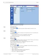
Page 68: ...a list of video exports Import system configuration will load previously saved system settings from a USB memory device Erase log book will delete the contents of the log book 6 11 2 Serial ports KBD KBD is used to set a unique ID number between 1 and 16 if multiple Divar XF units are controlled with one keyboard set a first camera number to create a multi Divar system for example Divar 1 has came...

Page 69: ...Divar XF Advanced configuration menu en 69 Bosch Security Systems Installation manual F 01U 135 429 2 5 2009 08 6 11 4 Logging Select the items to be logged Log contacts Log motion Log remote access ...

Page 70: ...70 en Advanced configuration menu Divar XF F 01U 135 429 2 5 2009 08 Installation manual Bosch Security Systems ...

Page 71: ...face 10 100 BaseT 7 1 2 Installing the Configuration Tool The Configuration Tool is optionally installed on the PC when the Control Center application is installed To install separately 1 Insert the CD ROM into the CD ROM drive on the PC The installation program starts automatically 2 If installation does not start automatically locate the Setup exe file on the CD and double click it 3 Follow the ...

Page 72: ... 2 Configuration Tool Edit Divar list To automatically detect all enabled Divar XFs on the network 1 Click Detect To detect a Divar XF Discovery must be enabled on that Divar XF 2 Select a Divar XF and click OK to add the selected Divar XF to the list To add a Divar XF to the list 1 Click Add 2 Enter the IP address or DNS name of the new Divar XF The IP address to be filled in is set in the Config...

Page 73: ...n is denied To let the system remember names and passwords on subsequent uses of the Configuration Tool place a check mark in the Save log on information box 3 Click Log on Maximum number of users If the maximum number of users eight is exceeded a window is displayed 7 2 1 Menu structure differences The Configuration Tool allows access to and use of unit menu items These menu items are explained i...

Page 74: ...that are to be filtered not viewed The latest event is shown first 7 3 3 Settings button Click Settings to display the page for configuring the Divar XF The menu tree structure and the selected subpage is shown in the center pane For more detailed information on the configuration settings please refer to Chapter 6 Advanced configuration menu Page 51 Using the Menu tree After clicking Settings the ...

Page 75: ...viewer do not change or edit them as this makes them unusable Import 1 Click Import to open a settings file 2 In the dialog box select the location and name of the file to open 3 Select the groups of settings to load and click OK 4 The selected settings are downloaded to the unit immediately Export 1 Click Export to save the current settings in a PC file 2 In the dialog box select the location and...

Page 76: ...5 429 2 5 2009 08 Installation manual Bosch Security Systems Factory Defaults Click the Factory Defaults button to set all settings on the active page to their default values Refresh Click Refresh to refresh the content of the current page settings only ...

Page 77: ...ll menu default values Navigation Setting Default value Reset International Language English N Time zone GMT 1 West Europe N Time format 24 hour N Time 0 00 N Date format DD MM YYYY N Date 1 1 2008 N IP address 0 0 0 0 N Schedule Week Monday Friday Y Week day 08 00 18 00 Y Weekend day 08 00 18 00 Y Recording Profile 1 6 Normal Resolution 4CIF Y Video quality Medium Y Frame rate 6 25 IPS Y Contact ...

Page 78: ...Quad 1 Yes Y Quad 2 Yes Y Quad 3 Yes Y Quad 4 Yes Y Sequence Monitor A B Sequence dwell time 5 Sec Y Sequence list Camera 1 16 Y Event display Monitor A B Change display on video loss Yes Y Change display on motion Yes Y Display duration 5 Sec Y Table 8 3 Configuration menu default values Navigation Setting Default value Reset International Language Language English N Temperature unit Celsius N Ti...

Page 79: ...Exception Days Empty Y Recording Profile 1 6 1 24 Normal Recording mode Continuous Y Pre event time 30 seconds Y Resolution 4CIF Y Video quality Medium Y Frame rate 6 25 IPS Y Record audio Disabled Y Audio quality Medium Y 1 24 Contact Contact recording Fixed duration Y Duration 30 seconds Y Resolution 4CIF Y Quality High Y Frame rate 25 IPS Y Record audio Disabled Y Audio quality Medium Y 1 24 Mo...

Page 80: ...n entering profile No actions Y Contact 1 24 Enabled 1 16 enabled Y Alarm Disabled Y Actions Apply recording for NShow on Mon A Y Motion 1 24 Enabled 1 16 Y Alarm Disabled Y Actions Apply recording for NShow on Mon A Video loss 1 24 Enabled 1 16 enabled Y Network Setup DVR Name DIVAR XF N Discovery Enabled N DHCP Enabled N IP address 0 0 0 0 N Subnet mask 0 0 0 0 N Default gateway 0 0 0 0 N HTTP p...

Page 81: ...llow configuration changes Disabled Y Allow playback Enabled Y Allow export Enabled Y Allow to delete recordings Disabled Y Control rights Camera viewing rights Enabled Y Camera control rights Enabled Y Allow camera pre positions Enabled Y Allow relay control Enabled Y System Service NA Serial ports ID 1 N First camera number 1 N Access for keyboard 1 4 Mon A Mon B Y Baud rate 38400 N Parity None ...

Page 82: ...82 en Menu default values Divar XF F 01U 135 429 2 5 2009 08 Installation manual Bosch Security Systems ...

Page 83: ...TSC auto detect Resolution 720 x 576 PAL 720 x 484 NTSC AGC Automatic adjustment or manual adjustment of gain for each video input Digital Zoom 1 5 6 times Compression H 264 Inputs Mono RCA 1 Vpp 10k ohm Outputs Dual mono RCA 1 Vpp 10k ohm Sample rate 48 kHz per channel Compression MPEG 1 layer II Inputs 8 or 16 configurable NO NC max input voltage 40 VDC Outputs 4 relay outputs 1 malfunction rela...

Page 84: ...26 16 0 13 1 5 mm2 Malfunction relay Screw terminal output via external adapter supplied cable diameter AWG 28 16 0 08 1 5 mm2 Biphase Screw terminal output via external PCB supplied cable diameter AWG 26 16 0 13 1 5 mm2 RS232 DB9 male 2 RS485 Screw terminal output via external adapter supplied cable diameter AWG 28 16 0 08 1 5 mm2 Keyboard input RJ11 6 pin Keyboard output RJ11 4 pin conform RS485...

Page 85: ...uded For mounting one unit in an EIA 19 inch rack Temperature Operating 5 C to 45 C 41 F to 113 F Storage 25 C to 70 C 13 F to 158 F Relative humidity Operating 93 non condensing Storage 95 non condensing EMC requirements USA FCC Part 15 Class B EU EMC directive 89 336 EEC Immunity EN50130 4 Emission EN55022 Class B Harmonics EN61000 3 2 Voltage fluctuations EN61000 3 3 Safety USA UL 60950 1 EU CE...

Page 86: ...e that the camera has been set up correctly and enough lighting is available In addition ensure that the camera is mounted so that it does not shake due to wind or other influences Frame rate IPS Resolution Quality 25 30 12 5 15 6 25 7 5 3 125 3 75 1 CIF Standard 225 124 73 48 30 CIF Medium 619 340 201 131 82 CIF High 1013 557 329 215 135 2CIF Standard 317 174 103 67 42 2CIF Medium 871 479 283 185...

Page 87: ......
Page 88: ...Bosch Security Systems Robert Koch Straße 100 D 85521 Ottobrunn Germany Telefon 089 6290 0 Fax 089 6290 1020 www boschsecurity com Bosch Security Systems 2009 ...

Reviews: