


Installation
Condens 7000 F – 6720871560 (2019/11)
18
5.7
Connecting the air supply (for room sealed operation)
NOTICE:
Damage to gaskets due to burred edges on the insertion ends of the
pipe parts!
▶ Make sure the insertion ends are free of burrs. If chamfering on site is
required, only do so in accordance with the manufacturer's
documentation.
The combustion air is supplied to the boiler either through an external
wall connection, a duct or a separate pipe in the duct.
The dimensions of the combustion air pipe must be calculated in
accordance with the current regulations.
An accessory set for room sealed operation is available for installation
inside the boiler casing (DN110 for boiler ratings 75-150 kW and
DN160 boiler ratings 200-300 kW).
▶ Only install the original accessories set envisaged for the
corresponding boiler rating.
We would recommend the installation of a silencer in the combustion air
pipe, subject to the location of the air inlet opening on the outside of the
building.
To avoid condensate formation in the combustion air pipe (inside and
outside), insulate the combustion air pipe.
For room sealed operation, both air intake and flue terminal positions
must be installed on the same side of the building, to prevent wind
effects.
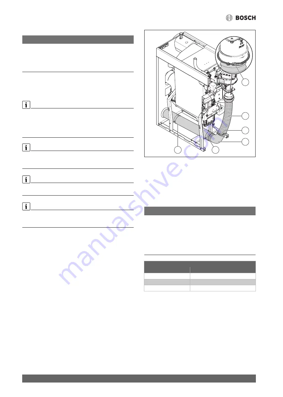
▶ Mount adapter (
Fig. 14, [6]) on the intake connector of the burner
and secure with hinged pipe clip.
▶ Push elbow [3] onto the combustion air pipe [1].
▶ Mount the combustion air pipe [1] with supplied pipe clips
[2, 2x] on the frame.
▶ Screw the combustion air hose [5] onto the adapter [6].
▶ Push the combustion air hose [5] onto the elbow and secure with
hose clip [4].
▶ In cascade arrangements, ensure that the boiler is equipped with a
separate combustion air pipe.
Fig. 14 Accessory set for room sealed operation
[1]
Combustion air pipe
[2]
Pipe clip (2x)
[3]
Elbow
[4]
Pipe clip
[5]
Combustion air hose
[6]
Adapter with hinged pipe clip
5.8
Hydraulic connection
NOTICE:
Risk of damage to system due to leaking connections!
▶ Install all lines free from stress to the boiler connections.
▶ Use new gasket if screw fittings need to be undone.
▶ Only tighten flanges in the heating flow and return after the
connections have been made.
▶ Before installing the pipe connections, check connections and
gaskets on the boiler for possible damage.
Table 7 Water connection dimensions
Boiler flow (VK)/Boiler return (RK)
Boiler size [kW]
Port
75-100
2" female thread (DN50)
150
PN6 standard flange EN1092 (DN50)
200-300
PN6 standard flange EN1092 (DN65)
0010012547-001
5
6
3
4
2
1