


1699502643 | REV. B | 05.2020
© Bosch Automotive Service Solutions Inc
ADS 525X
|
Quick Start Guide
|
15
|
en-US
Bosch Technical Support: (855) 267-2483
Fax: 1-800-955-8329
Please record and retain this important information:
Part No:
Serial No:
Purchase Date:
AutoDetect®
The new user interface utilizes graphic
“badges” to illustrate when critical
information is found. AutoDetect®
automatically detects vehicle-specific
solutions and graphically alerts the
user of on-tool or web-based repair
information found. To use the Code To
Fix® feature, press the Diagnostic Trouble
Code to launch the DTC Info screen for
access to exclusive experienced-based
fixes and repair information for that
specific vehicle and DTC.
Connected to 2008 Ford F-150 King Ranch 5.4L
10:22
Change Vehicle
Home
Connected
10:22
Change Vehicle
Home
DTC Scan
Change Vehicle
Scan Complete. Tap any item to see error codes
Add Image(s) to Report
PCM / PATS
P0030 - Fail Since Clear - Heated Oxygen Sensor Heater Control Circuit Sensor 1
P0036 - Fail Since Clear - Heated Oxygen Sensor Heater Control Circuit Sensor 2
P0016 - MIL Codes - Crankshaft Position (CKP) -Camshaft Position (CMP) Correlation
INSTRUMENT CLUSTER
4X4 CONTROL
3 DTC(S) found
3 DTC(S) found
3 DTC(S) found
Clear DTCs
Refresh
Share
Save
Home
Details
Details
Details
rt0015
Connected to 2008 Ford F-150 King Ranch 5.4L
Connected
10:22
P0030
Change Vehicle
Heated Oxygen Sensor Heater Control Circuit Sensor 1
Description
Description
Mitchell
Diagnostics
System Wiring
Measures the amount of oxygen in the exhaust gas and sends a corresponding
signal to the ECM/PCM. The ECM/PCM uses this signal to help maintain an
optimum air/fuel ratio. The sensor has a heating element to allow quicker closed
loop operation.
Code Criteria
Code Assist
Location
Scan Test
PCM Pin
Help
Home
IDENTIFI
FIND AND FIX FASTER
6604
Online R
esour
ce
s
rt0017
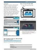
How to Power Off ADS 525X
a. Press and release the power
button.
Connected
Generic OBDII
Repair-Source
10:22
QuickScan
Apps Shortcut
Settings
What’s New
Web Browser
Coverage Guide
Video Tutorials
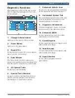
Diagnostic Information
Wiring Diagrams
i
i
Saved Reports
Main Menu
Diagnostics
b. Select Power Off. The tool will now
shutdown.
Connected
Generic OBDII
Repair-Source
10:22
QuickScan
Apps Shortcut
Settings
What’s New
Web Browser
Coverage Guide
Video Tutorials
Diagnostic Information
Wiring Diagrams
i
i
Saved Reports
Main Menu
Diagnostics
Power off
Restart
rt0018
Note: When switching vehicles, it is best
to return to the home screen before
disconnecting the VCI from the vehicle to
avoid communication errors.


