-10-
Operating Instructions
VARIABLE SPEED CONTROLLED
TRIGGER SWITCH
Your tool is equipped with a variable speed
trigger switch. The tool speed can be
controlled from the minimum to the maximum
nameplate speed by the pressure you apply
to the trigger. Apply more pressure to
increase the speed and release pressure to
decrease speed. This accurate speed control
enables you to drill without center punching.
It also permits you to use as a power
screwdriver. Bits are available for driving
screws as well as running bolts and nuts.
REVERSING SWITCH LEVER
This tool is equipped with a rotating brush
reversing system. This results in longer brush
life while maximizing power in both forward and
re verse directions. The reverse switch can be
oper ated from either the right or left side of the
tool.
FOR FORWARD ROTATION: slide switch to
arrow marked forward (Fig. 1).
FOR REVERSE RO TATION: slide the slide
switch to arrow marked re verse. NOTE: Tool
will not operate in middle position.
SLIP CLUTCH
The tool has an internal preset clutch. The
clutch is set such that sufficient force is
transmitted to the bit for most drilling
conditions but it will slip when bit binds in the
hole or the tool is overloaded. Be aware that
due to required clutch setting, you may
experience a torque reaction an instant
before the clutch slips. This torque reaction
will twist the body of the rotary hammer in the
opposite direction as the bit rotates, i.e.,
counterclockwise. As clutch is slipping, the
bit will most likely stop rotating. When the
binding force on the bit is removed the clutch
automatically resets. If you experience bit
binding and clutch begins to slip, immediately
turn the tool "OFF" and correct the condition
leading to the bit binding.
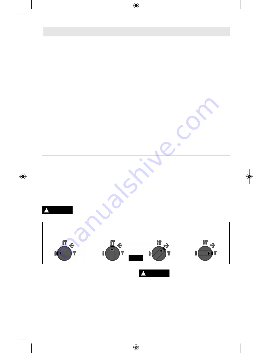
SELECTOR DIAL
The selector dial allows the tool to be set for
various drilling/hammer drilling applications.
Depress release button and turn selector dial
right or left depending on the below applications.
When using demolition or chipping bits such as
bull points, chisels, spades, gouges, etc. the
“Hammer Only” mode must be selected.
Do not operate the selection dial until the
tool come to a complete
stop.
Shifting during rotation of
the chuck can cause damage to the tool.
SELECTOR DIAL - “VARIO-LOCK”
Adjusting the Vario-Lock: The vario-lock
can be set in any one of thirty-six (10˚
increments) positions. Choose a position
which is best suited for your operation.
Depress release button and turn the selector
dial, to the “vario-lock” setting. Next, rotate
the locking sleeve, along with the accessory,
to the desired position. Then turn the selector
dial to the “hammer only” setting and slightly
turn the locking sleeve to have it
automatically lock into a definite position.
!
CAUTION
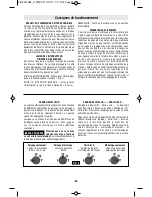
Drilling only: Drilling/hammering: Vario-lock Hammering only:
used for drilling
used for drilling allows for 36 desired used for light
wood, steel, etc. concrete positions of “hammer” chipping work
FIG. 6
HAMMERHOOK
™
(Model 11255VSR & RH226 only)
Your tool is equipped with a convenient hook
for hanging your tool. To use, simply open hook
until it snaps into the open position (Fig. 7).
When using the HAMMERHOOK™ always
be aware that the accessory is exposed.
Always hang the tool in an area where
yourself and bystandards can not accidently
make contact with the accessory.
To reduce the risk of
injury,
use
care
in
selecting the location for hanging the
tool.
• Select a suitably sized and shaped object
that will provide adequate hanging stability.
An unstable hanging surface could result in
the tool unexpectedly falling.
• Insure that the tool is hung out of the way of
!
WARNING
2610047983_11253VSR 10/2/17 1:10 PM Page 10


