


V3.2
3
V3.2
Preparation
6
How To Change Your Code Number
Fitting the Hexagonal Support Posts
Fit both of the hexagonal support posts
(part no.6)
into the top and
bottom threaded holes of the keypad, as shown in arrows
A
and
B
in the
diagram on the right.
Without the hexagonal support posts fitted the machine screws will not be
able to be screwed into place, as they are different thread sizes.
Do not over tighten the hexagonal support posts as this may strip the
thread on either the post itself or the thread in the back of the keypad.
How To Change Your Code Number
Preparation
1
2
3
4
5
6
7
F
B
A
↓ ↓
↓
↓
Please note:
The keypad has a double button press function and you are able to have the same digit twice. When
the unit is being coded, if the green marker of the coding disk is in alignment with the centre line arrow on the cover
plate it denotes that the button is set as a double press. If the red marker of the coding disk is inalignment with the
centre line arrow it is set for a single press and if blue marker of the coding disk is in alignment with the centre line
arrow it is not part of the code.
The coding chamber is non-sequential so the code can be entered in any order. If for instance the unit was coded
to 11234
(as per fig.4 below)
, the unit can be opened by entering 11432, 43211, 12314 etc...
1.
To change the code the unit will need to be removed from the door or done prior to fitting.
2.
Turn the keypad over and remove the extension plate (if fitted) so that the back of the coding chamber is visible.
The extension plate is secured to the keypad by 2 x retaining screws. Turn the lever handle of the keypad to ensure
that the coding chamber is reset before a new code is to be programmed.
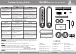
3.
With the coding chamber reset you will see that the coding disks are set to what the keypad is currently coded
to. If for instance the unit is coded to 11234; the number 1 disk will have the green marker of the coding disk lined
up with the centre line arrow on the cover plate. The number 2, 3 and 4 will have the red marker of the coding disks
lined up with the centre line arrow
(as per fig.4)
. All the other coding disks will have the blue line in alignment with
the centre line arrow.
4.
Choose what the unit wants to be coded to. To change how a button is set in the code – insert the code change
tool
(part no.12)
into the small hole in the top of the inner gear and then it can be lifted upwards, this will expose a
red line on the inner gear
(as per fig.5)
.
Fig.4
↓
↓
Centre Line
Arrow
1
2
3
4
↓
↓
Coding
Disk
Code Change
Tool
Inner
Gear
1
2
3
4
Fig.5
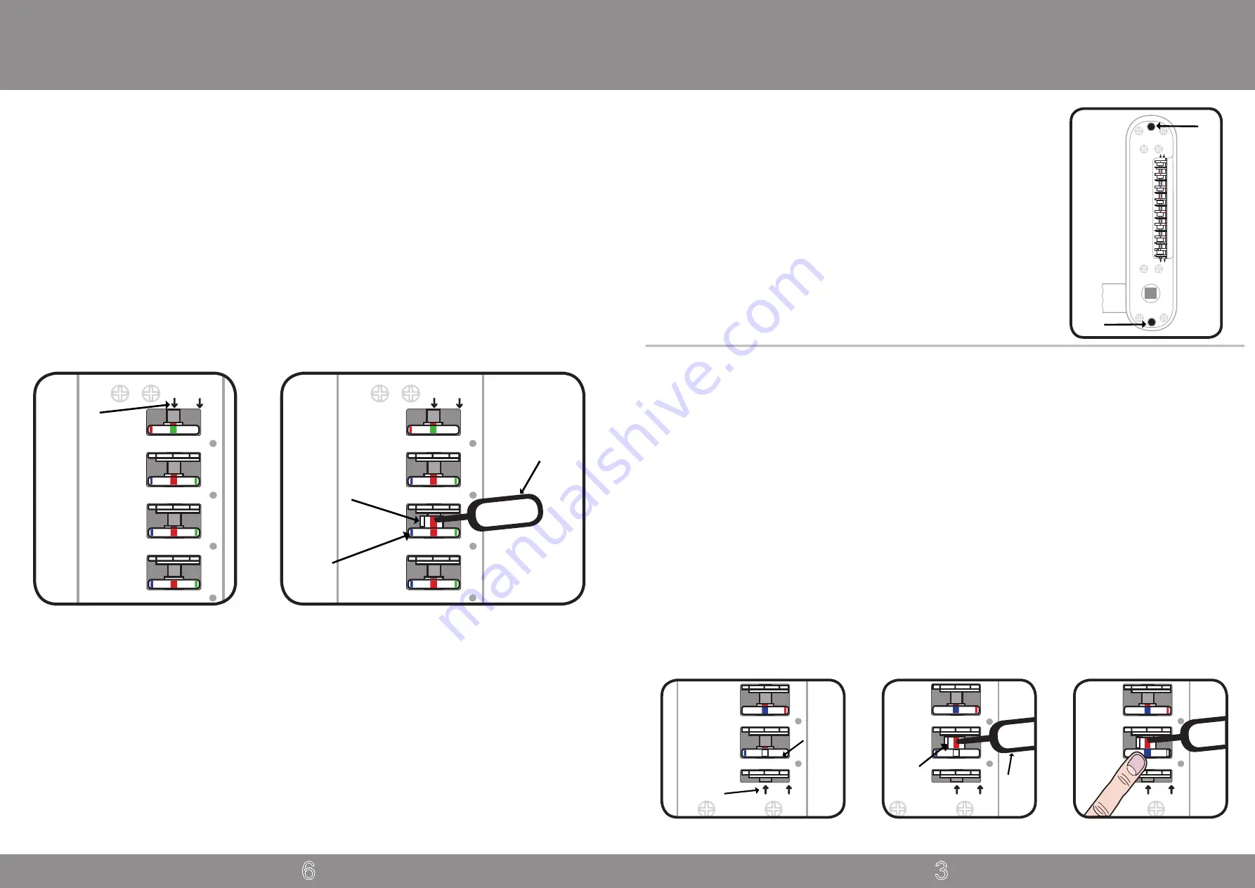
Turning off the Free Passage Function
All units are supplied with the free passage function ready to be used, unless you have specifically ordered with the
function turned off. If you do not require the free passage function this feature can be turned off, this should be done
before the unit is fitted to the door.
If your unit has the free passage function turned on, the white line of the ‘F’ coding disk will be in alignment with the
centre line arrow
(as per fig.1)
. If it is turned off the blue line of ‘F’ coding disk will be in alignment with the centre
line arrow.
1.
To turn off the free passage function – insert the code change tool
(part no.12)
into the small hole in the top of the
inner gear and then it can be lifted upwards, this will expose a red line on the inner gear
(as per fig.2)
.
2.
Whilst holding the inner gear the coding disk can be rotated using your finger. Rotate the disk until the blue line of
the coding disk is in alignment with the red line of the inner gear
(as per fig.3)
.
3.
With the blue line in position, the inner gear can be released and it should drop into position. The inner gear and
tab should no longer be visible. If the inner gear is still exposed after releasing, rotate the coding disc with your finger
to the left until the inner gear drops into position.
If at a later date you wish to turn back on the free passage function, follow the above steps but instead of setting the
blue line of the coding disk set the white line.
F
↓
↓
Fig.1
Coding
Disk
7
7
F
↓
↓
Code
Change
Tool
Inner
Gear
Fig.2
F
↓
↓
7
Fig.3
Centre Line
Arrow


