


6
zero”, which is mechanically linked with the bridge control, really closes, as otherwise
the zero-position can not be adjusted.
14.
The programming of the zero-position is now also done as described under 6.
(pushing of the takeover-button for app. 1 sec.). If there is no optic acknowledgement
(2 sec. permanent light), the micro-switch “position zero” at the controller of the bridge
control unit is not closed. Please check again.
15.
The jumper between terminals 37 and 38 is now removed to quit the programming
mode. The power supply can remain switched on during this procedure. In case of
correct programming, normal operation starts immediately.
After every programming step and after every activation, the installed software checks the
conclusiveness of all programmed adjusting values. If they are not conclusive (e. g. min.-
value higher than max.-value), the failure-relay K4 is activated and the lamp „ready for
operation“ flashes in a 5-second-cycle; 1 sec. on, 4 sec. off.
Possible mistakes are, e. g., mix-up of the exterior controller connections (at max. positive
propeller angle, the voltage at the slider has to be higher than in zero-position) or a wrong
position of the selector switch (operation), whose labelling has a different meaning during
programming. Anyway, in case of such a mistake, the whole programming procedure has to
be repeated. The same applies, if there is a power failure during the programming phase.
If necessary, a new adjustment can be done later at any time. Here, it is also possible to only
program single positions, e. g. only position angle zero --> follow instructions 1, 2, 11 to 15.
If the stored adjustment parameters shall be taken down, the installed EEPROM has to be
removed for a short time and has to be read with a separate programming device.
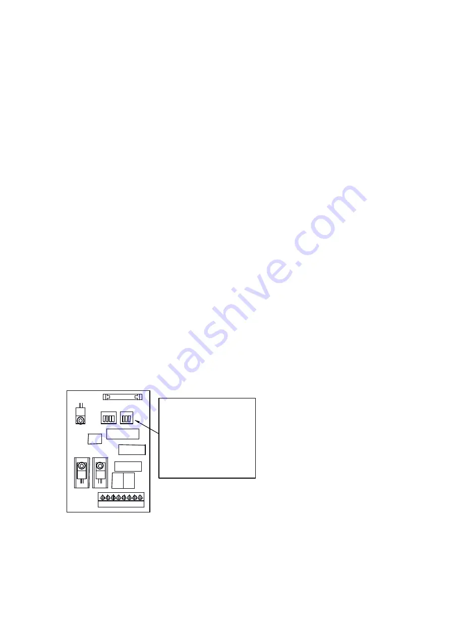
DIP-Switch on Additional Module AHD 903IP
The size of the close-up range can be specified qualitatively as binary value with 6 DIP-
switches in a range of 0-63. The value is proportional to the adjustable angle and has to be
adjusted iteratively depending on the overall order. The close-up range is adjusted on the
value 32 at delivery.
1 2
3
4 5
6 7
8
1
1
2
2
3
3
4
SW 1
SW 2
Ansicht auf die Ausgabeein-
heit AHD 903IP von oben
ohne Abdeckung
DIP-Schalter SW 1, SW2
zur Einstellung des Nah-
bereichs
View of the output-unit
AHD 903IP from
above without cover.
Dip-switch SW1, SW2
for adjustment of
minimum range