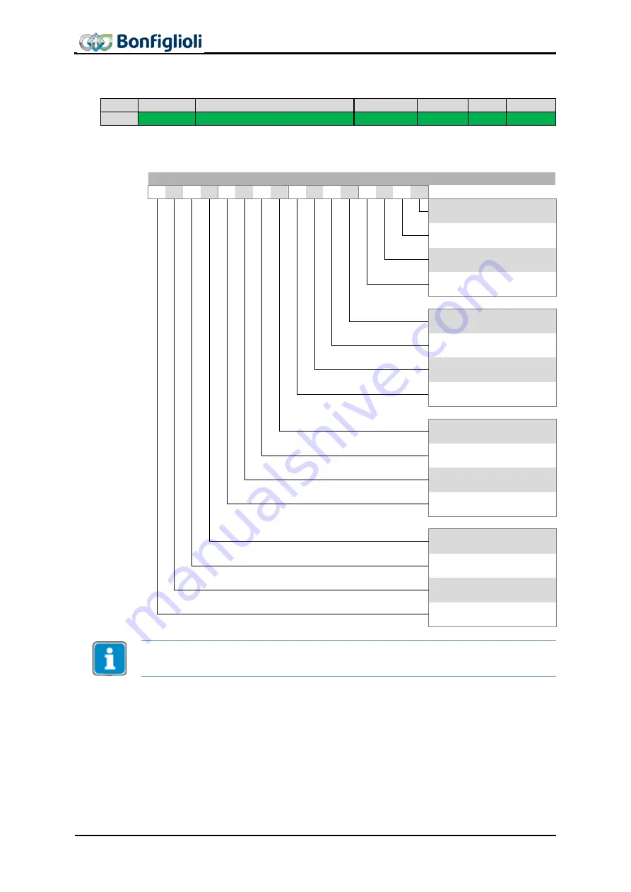
background image


12.5.3


0x6040/0 Control word  


Index  Sub-index 

Meaning 

Data type  Access   Map  Def.-Val 


0x6040 

Control word 

Unsigned16 

rw 

Rx 


Object 0x6040/0 

Control word is relevant to the inverter remote state machine whenev-

er parameter 

Local/Remote

 412 is set to 1 (remote state machine). 


Control word (Control word) 


15  14  13  12  11  10  9  8  7  6  5  4  3  2  1  0  Bit 


Switch on


Enable voltage


Quick stop (Low active)


Enable operation


Operation mode specific


Operation mode specific


Operation mode specific


Fault reset


Halt


Operation mode specific


10 

Reserved


11 

Manufacturer specific


12 

Manufacturer specific


13 

Manufacturer specific


14 

Manufacturer specific


15 

Manufacturer specific


Bits 4, 5, 6 and 9 … 15 are used in motion control configurations (p.30 = x40) only. 

See chapter 14 “Inverter Control” and 16.1.1 “Control Word overview”


72 

CM-EtherCAT 

07/13 


Summary of Contents for ACTIVE CUBE Series

Page 1: ...ACTIVE CUBE EtherCAT Communication module CM EtherCAT Frequency inverter 230 V 400 V ...

Page 2: ......

Page 3: ...2 6 8 Information signs 14 2 7 Directives and guidelines to be adhered to by the operator 15 2 8 Operator s general plant documentation 15 2 9 Operator s operating staff s responsibilities 15 2 9 1 Selection and qualification of staff 15 2 9 2 General work safety 15 2 10 Organizational measures 15 2 10 1 General 15 2 10 2 Use in combination with third party products 16 2 10 3 Transport and Storage...

Page 4: ...r 42 12 2 3 0x1008 0 Manufacturer Device Name 43 12 2 4 0x1009 0 Manufacturer Hardware Version 43 12 2 5 0x100A 0 Manufacturer Software Version 43 12 2 6 0x1010 n Store Parameters 43 12 2 7 0x1011 n Restore default Parameters 44 12 2 8 0x1018 n Identity Object 44 12 2 9 0x1600 n 0x1601 n 0x1602 n RxPDO Mapping Parameter 45 12 2 10 0x1A00 n 0x1A01 n 0x1A02 n TxPDO Mapping Parameter 46 12 3 Manufact...

Page 5: ...ort 75 12 5 8 0x6046 n Velocity min max amount 75 12 5 9 0x6048 n Velocity acceleration 77 12 5 10 0x6049 n Velocity deceleration 78 12 5 11 0x604A n Velocity quick stop 79 12 5 12 0x6060 0 Modes of operation 80 12 5 13 0x6061 0 Modes of operation display 81 12 5 14 0x6064 0 Position actual value 81 12 5 15 0x6065 0 Following error window 82 12 5 16 0x6066 0 Following error time out 83 12 5 17 0x6...

Page 6: ...gurations 127 14 3 1 Behaviour in quick stop 127 14 3 2 Behaviour in transition 5 Disable operation 128 14 3 3 Reference value actual value 129 14 3 4 Example Sequence 130 14 4 Motion control configurations 131 14 4 1 Velocity mode rpm 132 14 4 1 1 Example Sequence 135 14 4 2 Profile Velocity mode u s 137 14 4 2 1 Example Sequence 140 14 4 3 Profile position mode 141 14 4 3 1 Example Sequence 147 ...

Page 7: ... 16 2 Warning messages 192 16 3 Warning Messages Application 193 16 4 Fault messages 194 16 5 Conversions 195 16 5 1 Speed rpm to Frequency Hz 195 16 5 2 Frequency Hz to Speed rpm 195 16 5 3 Speed in user units u s to Frequency Hz 195 16 5 4 Frequency Hz to Speed in user units u s 195 16 5 5 Speed in user units u s to Speed rpm 195 16 5 6 Speed rpm to Speed in user units u s 195 16 6 Object suppor...

Page 8: ...plete functionality of the frequency inverter The parameters required for special purposes for adjustment to the application and the numerous additional functions are described in detail Separate user manuals are supplied for optional components for the frequency inverter These manu als complement the operating instructions and the Quick Start Guide for the frequency inverter Application manual Th...

Page 9: ...anual do not form part of any previous or existing agreement assurance or legal relationship Neither are they intended to supplement or replace such agreements assurances or legal relationships Any obligations of the manufacturer shall solely be based on the relevant purchase agreement which also includes the complete and solely valid warranty stipulations These contractual warranty provisions are...

Page 10: ...efeld Germany These user manual is intended for the operator of the frequency inverter Any disclosure or copying of this document exploitation and communication of its contents as hardcopy or electronically shall be forbidden unless permitted expressly Any non compliance will constitute an offense against the copyright law dated 09 September 1965 the law against unfair competition and the Civil Co...

Page 11: ...ir and troubleshooting Based on their qualifi cation and or know how qualified staff must be capable of identifying defects and assessing func tions Qualified electrician The term Qualified Electrician covers qualified and trained staff who has special technical know how and experience with electrical installations In addition Qualified Electricians must be familiar with the applicable standards a...

Page 12: ... shall not be held liable for any damage resulting from such misuse The sole risk shall be borne by the operator 2 3 1 Explosion protection The frequency inverter is an IP 20 protection class device For this reason use of the device in explo sive atmospheres is not permitted 2 4 Residual risks Residual risks are special hazards involved in handling of the frequency inverter which cannot be elim in...

Page 13: ...sk of death or serious injury if not avoided CAUTION Identification of immediate threat holding a low risk of minor or moderate physical inju ry if not avoided NOTE Identification of a threat holding a risk of material damage if not avoided 2 6 2 Hazard symbols Symbol Meaning Symbol Meaning General hazard Suspended load Electrical voltage Hot surfaces 2 6 3 Prohibition signs Symbol Meaning No swit...

Page 14: ... reuse 2 6 6 Grounding symbol Symbol Meaning Ground connection 2 6 7 ESD symbol Symbol Meaning ESD Electrostatic Discharge can damage components and assemblies 2 6 8 Information signs Symbol Meaning Tips and information making using the frequency inverter easier 14 CM EtherCAT 07 13 ...

Page 15: ...ormed by a qualified electrician according to the applicable rules of electrical engineering The operating staff must be trained for the relevant work to be performed 2 9 2 General work safety In addition to the user manual of the machine plant any applicable legal or other regulations relating to accident prevention and environmental protection must be complied with The staff must be instructed a...

Page 16: ...l overloading of the frequency inverter Do not bend any components and never change the isolation distances Do not touch any electronic construction elements and contacts The frequency inverter is equipped with components which are sensitive to electrostatic energy and can be damaged if handled improperly Any use of damaged or destroyed components will endanger the ma chine plant safety and shall ...

Page 17: ...he capacitor in the DC link is dis charged Wait for at least 3 minutes after shutdown before starting electrical or mechanical work on the frequency inverter Even after this waiting time make sure that the equipment is deener gized in accordance with the safety rules before starting the work In order to avoid accidents or damage only qualified staff and electricians may carry out the work such as ...

Page 18: ...ac turer or persons authorized by the manufacturer Check protective equipment regularly Before performing any maintenance work the machine plant must be disconnected from mains supply and secured against restarting The five safety rules must be complied with 2 10 8 Final decommissioning Unless separate return or disposal agreements were made recycle the disassembled frequency in verter components ...

Page 19: ...Object support in the Software versions and XML for information on the required objects and XML files This manual is not to be understood as providing general basic information on Ether CAT It requires basic knowledge of the methods and effects of EtherCAT on the user s side In some chapters setting and display options via the PC software VPlus are described as an alternative to the KP500 control ...

Page 20: ...56 29 NOTE With the CM EtherCAT communication module it is possible to access ALL frequency inverters parameters from a controller There is no ac cess control via the control level as in the case of the KP500 manual control unit or the VPlus PC software Changing parameters the func tions of which are not known to the user can result in unintended movements and material and or personal losses as we...

Page 21: ...42 target velocity o Percentage reference value for technology controller or Torque control Analogue input Fixed values from parameters Please refer to chapter 14 3 Non motion control configurations for the control without Positioning functionality Positioning via contacts or remote contacts Necessary settings Configuration 30 x40 Local Remote 412 Remote contacts The control Start Stop Target posi...

Page 22: ...e function via PLC o PDO Mapping Chapter 12 2 9 12 2 10 o Fault reaction Chapter 10 12 5 1 Fault reset Chapter 16 4 11 9 Setting Reference value o Speed setting in speed controlled configura tion x10 x11 x15 x16 x30 x60 Chapter o Reference value in Positioning configuration x40 Chapter 13 and Velocity Mode Chapter 14 4 1 Profile Velocity Mode Chapter 14 4 2 Profile Position Mode Chapter 14 4 3 Hom...

Page 23: ...module otherwise compo nents may be damaged Work steps Disconnect the frequency inverter from the mains voltage and protect it against being energized unintentionally Remove covers 1 and 2 of the frequency inverter Slot B 4 for the com munication module is now accessible 1 2 3 Slot A Slot B Mount the supplied PE spring 5 using the M4 screw 6 in the unit The spring must be aligned centrally Insert ...

Page 24: ...where the looking hooks 10 for the upper cover 1 project from the case of the frequency inverter To do this carefully insert the screwdriver in the gap between the case of the module and the frequency inverter and push the locking hook inwards in the direction of the arrow As soon as the right hand side is unlocked pull the module out a bit on the right hand side and hold it Hold the module on the...

Page 25: ...hernet cables with RJ45 connectors Ethernet standard IEEE 802 3 100Base TX fast Ethernet Cable type S FTP cable with braided shield ISO IEC 11801 or EN 50173 Straight Through or Cross Over Connections from the POC are connected to IN Connections to the next device are connected to OUT 07 13 CM EtherCAT 25 ...

Page 26: ...nction 0 No Reaction Operating point is maintained 1 Error Device state machine changes immediately to state fault factory setting 2 Switch off Device state machine processes command disable voltage and changes to state switch on disabled 3 Quick Stop Device state machine processes command quick stop and changes to state switch on disabled 4 Ramp Stop Error Device state machine processes command d...

Page 27: ...ication Objects The communication objects are located in the index range 0x1nnn They describe the communication behaviour of an EtherCAT device Some of the communication ob jects comprise device information e g manufacturer s vendor id or inverter serial number With the help of communi cation objects the application objects for device control are mapped to the PDO mes sages 11 2 Application Object...

Page 28: ...um 0x0607 0x0010 Data type does not match Parameter has a different data type 0x0607 0x0012 Data type does not match or length of Service tele gram too big Parameter has a different data type or telegram length not correct 0x0607 0x0013 Data type does not match or length of Service tele gram too small Parameter has a different data type or telegram length not correct 0x0609 0x0011 Subindex does no...

Page 29: ...nt error information After error acknowledgement fault reset an emergency message is sent with all data bytes set to zero Byte Byte 0 Byte 1 Byte 2 Byte 3 Byte 4 Byte 5 Byte 6 Byte 7 Content EEC EEC ER MEC MEC EEC Emergency Error Code according to DS301 ER Emergency Register Code according to DS301 MEC Manufacturer Error Code The Manufacturer Error Code corresponds to the inverter Fault codes that...

Page 30: ...ible NMT state changes NMT State Description Init Initialising No SDO Communication No PDO Communication Pre Operational Fieldbus active SDO Communication No PDO Communication Safe Operational Fieldbus active SDO Communication PDO Communication o IN data TxPDO s from inverter application send to PLC master o OUT data RxPDO s blocked not transferred to application in inverter Operational Fieldbus a...

Page 31: ...stembus 3 Ind Ethernet Module The OS is synchronized via Ethernet Module 4 Synchronised Ind Ethernet Module The OS is synchronized via synchronized Ethernet Module e g EtherCAT 99 Off The OS is not synchronized with other devices Operation mode Auto The selection is done via this decision table EtherCAT active Systembus active Synchronization Yes Yes Synchronisation via EtherCAT Yes No No Yes Sync...

Page 32: ...s Shows the Synchronization cycle 849 CANopen SYNC position 1ms Task us Shows the Synchronization time inside 1 ms Should remain constant with small fluctuations 11 9 Fault Reset Depending on the settings and the operating status of the device a fault reset can be done like described When using control via parameter Local Remote 412 Statemachine Set bit 7 in 0x6040 Control word 0x0080 Via the Stop...

Page 33: ...igned 16 Bit value 215 215 1 0x8000 0x7FFF 32768 32767 Integer8 Signed 8 Bit value 27 27 1 0x80 0x7F 128 127 Visible string String up to 99 characters long Transmission via Segment ed Transfer PDO Mapping No This object cannot be used for PDO exchange only SDO is applicable Tx This object can be transmitted as PDO from ACU Rx This object can be transmitted as PDO to ACU Highest Sub index supported...

Page 34: ...meter 0 No of mapped objects Read Write Unsigned8 No 1 1 mapped obj Read write Unsigned32 No 2 2 mapped obj Read write Unsigned32 No 3 3 mapped obj Read write Unsigned32 No 4 4 mapped obj Read write Unsigned32 No 5 5 mapped obj Read write Unsigned32 No 6 6 mapped obj Read write Unsigned32 No 7 7 mapped obj Read write Unsigned32 No 8 8 mapped obj Read write Unsigned32 No 0x1602 RxPDO3 mapping param...

Page 35: ...ital In actual values Read only Unsigned16 Tx 0x3002 0 Digital Out actual values Read only Unsigned16 Tx 0x3003 0 Digital Out set values Read write Unsigned16 Rx 0 0 0x1F 0x3004 0 Boolean Mux Read only Unsigned16 Tx 0x3005 0 Boolean Demux Read write Unsigned16 Rx 0 0 0xFFFF 0x3006 0 Percentage set value Read write Unsigned16 Rx 0 0x8AD0 0x7530 0x3007 0 Percentage actual value 1 Read only Unsigned1...

Page 36: ...celeration Read write Unsigned32 No 0x0005 0000 1 0x7FFF FFFF p 1127 DS4 0x5F15 0 In Gear Threshold Read write Unsigned32 No 0 0 0x7FFF FFFF p 1168 0x5F16 0 In Gear Time Read write Unsigned16 No 10 1 0xFFFF p 1169 0x5F17 Position Controller v u h i p t g 0 Highest sub index supported Read only Unsigned8 No 1 Time Constant ms Read write Integer32 No 10 00 1 00 300 00 p 1104 2 Limitation Read write ...

Page 37: ... sub index supported Read only Unsigned8 No 1 Delta speed Read write Unsigned32 No 150 1 32767 p 424 2 Delta time Read write Unsigned16 No 1 1 65535 p 425 0x6060 0 Modes of operation Write only Integer8 Rx 2 3 9 0x6061 0 Modes of operation display Read only Integer8 Tx 2 0x6064 0 Position actual value Read only Integer32 Tx 0x8000 0000 0x7FFF FFFF p 1108 0x6065 0 Following error win dow Read write...

Page 38: ... zero Read write Unsigned32 No 0x0002 0000 1 0x7FFF FFFF p 1133 0x609A 0 Homing acceleration h Read write Unsigned32 No 0x0005 0000 1 0x7FFF FFFF p 1134 0x60C1 Interpolation data record i 0 Highest sub index supported Read only Unsigned8 No 1 Interpolation data record 1 Read write Integer32 Rx 0 0x8000 0000 0x7FFF FFFF 0x60F4 0 Following error actual value Read only Integer32 Tx p 1109 0x60F8 0 Ma...

Page 39: ... written and saved and then the corresponding inverter parameter was set by e g VPlus the next power on cycle overwrites the value set by VPlus with the value stored by the save com mand Effect of the save command Object 0x1010 sequences of writing parameters and objects examples Sequence 1 P 419 48 Hz 3 P 419 48 Hz 2 Power OFF ON VPlus KP500 VPlus KP500 1 P 419 48 Hz 4 P 419 48 Hz 3 Power OFF ON ...

Page 40: ...8 Hz at KP500 or in VPlus 2 Setting of CANopen object 0x6046 1140 rpm equivalent to 38 Hz 3 Save command via CANopen object 0x1010 4 Setting of Maximum Frequency 419 48 Hz at KP500 or in VPlus 5 Power OFF and ON 6 Value of CANopen object 0x6046 overwrites the parameter value The value of CANopen object 0x6046 is active 38 Hz Internal conversion to a frequency value taking into account the No of Po...

Page 41: ...entification is carried out during the start of the network The infor mation on the device type and the functionality type are prescribed by the CANo pen standards Object 0x1000 0 Additional Information Device Profile Number Mode Bits Type 31 24 23 16 15 0 The Drives and Motion Control standard device profile used by the frequency in verter is portrayed as device profile number 402 The additional ...

Page 42: ... about the current device fault can be checked VPlus with pa rameter Actual Error 259 and 260 via EtherCAT see chapter 16 4 Fault messag es Also the emergency message contains additional information which can be evaluat ed by the PLC see chapters 11 5 Emergency Function and 12 5 2 0x603F 0 Error code Object 0x1001 0 7 6 5 4 3 2 1 0 Bit 0 General error 1 Current 2 Voltage 3 Temperature 4 Communicat...

Page 43: ... Visible string ro No See Text The software version is displayed as a sequence of ASCII characters Example 5 4 0 12 2 6 0x1010 n Store Parameters Index Sub index Meaning Data type Access Map Def Val 0x1010 0 Highest sub index supported Unsigned8 ro No 3 1 Store all parameters Unsigned32 r w No See text 2 Store communication parameters Unsigned32 r w No See text 3 Store application parameters Unsig...

Page 44: ...ults com mand is not processed 12 2 8 0x1018 n Identity Object The identity object provides information on the device manufacturer as well as the device itself Index Sub index Meaning Data type Access Map Def Val 0x1018 0 Highest Sub index supported Unsigned8 ro No 4 1 Vendor ID Unsigned32 ro No See text 2 Product code Unsigned32 ro No See text 3 Revision number Unsigned32 ro No See text 4 Serial ...

Page 45: ...ers 0x1600 n RxPDO1 0x1601 n RxPDO2 0x1602 n RxPDO3 0x1600 0 0 no objects mapped 0x1600 0 1 8 1 8 objects mapped Mapping entry MSB LSB Object index Subindex Length no of bits High byte Low byte si ll Examples Mapping of 0x6040 0 Control word unsigned16 10hex to 1st mapped object in RxPDO1 0x1600 1 0x60400010 Mapping of 0x60C1 1 interpolation data record 1 integer32 20hex to 2nd mapped object in Rx...

Page 46: ...rameters 0x1A00 n TxPDO1 0x1A01 n TxPDO2 0x1A02 n TxPDO3 0x1A00 0 0 no object mapped 0x1A00 0 1 8 1 8 objects mapped Mapping entry MSB LSB Object index Subindex Length no of bits High byte Low byte si ll Examples Mapping of 0x6041 0 Status word unsigned16 to 1st mapping object inTxPDO1 0x1A00 1 0x60410010 Mapping of 0x6064 0 position actual value integer32 to 2nd mapping object in TxPDO1 0x1A00 2 ...

Page 47: ...ata values are set via data set 0 all four data sets are set to the same transmitted value A read access with data set 0 to such parameters is only successful if all four data sets are set to the same value If this is not the case an error is reported NOTE The values are entered automatically into the EEPROM on the controller If values are to be written cyclically there must be no entry into the E...

Page 48: ... 1211 No of Repetitions 1212 Delay 1213 Delay Next Motion Block 1214 Event 1 1215 Event1 Next Motion Block 1216 Event 2 1217 Event2 Next Motion Block 1218 Digital Signal 1 1219 Digital Signal 2 1247 Digital Signal 1 1248 Digital Signal 2 1260 Interrupt Event 1 1261 Int Event 1 Eval Mode 1262 Int Event 1 Next Motion Block 1263 Interrupt Event 2 1264 Int Event 2 Eval Mode 1265 Int Event 2 Next Motio...

Page 49: ...s written during commissioning or regularly at simple positioning applications Writing Parameter 1202 Target Position Distance Type long in Index 1 into RAM index 34 for write access with Parameter value 30000 Index 1200 0x2000 0x24B0 Value int 34 0x0022 Index 1202 0x2000 0x24B2 Value long 30000 0x0000 7530 If several parameter of an index should be changed it is sufficient to set the index access...

Page 50: ...nctional input 1 if in Operation mode 452 digital input as de scribed in parameter Digital Inputs 250 12 4 2 0x3002 0 Digital Out actual value Index Sub index Meaning Data type Access Map Def Val 0x3002 0 Digital Out actual value Unsigned16 ro Tx Object 0x3002 Digital Out actual value displays the current state of the up to 4 de pending on optional hardware digital outputs and of the multifunction...

Page 51: ...ces as operation mode 90 94 Obj 0x3003 DigOut 1 5 respectively inverted as 190 194 inv Obj 0x3003 DigOut 1 5 see e g parameter Op Mode Digital Output 1 530 The mapping of this object bits to the outputs is arbitrary Example Function Parameter no Choice list excerpt Op Mode Digi tal Output 3 532 0 OFF 1 Ready or Standby Signal 2 Run Signal 43 External Fan 90 Obj 0x3003 Digout 1 91 Obj 0x3003 Digout...

Page 52: ...urce Bit number 0 15 corresponds with index number 1 16 The sources for the 16 bits can be chosen from a choice list via the index parameter CANopen Mux Input 1422 Parameters 1420 and 1421 are the associated write and read parameters which you have to set prior to writing reading parameter 1422 By using VTable this process is easier and more clearly laid out For writing and reading index parameter...

Page 53: ... list Obj 0x3005 Bit no Source No Source name 0 832 Obj 0x3005 Demux Out 1 1 833 Obj 0x3005 Demux Out 2 2 834 Obj 0x3005 Demux Out 3 3 835 Obj 0x3005 Demux Out 4 4 836 Obj 0x3005 Demux Out 5 5 837 Obj 0x3005 Demux Out 6 6 838 Obj 0x3005 Demux Out 7 7 839 Obj 0x3005 Demux Out 8 8 840 Obj 0x3005 Demux Out 9 9 841 Obj 0x3005 Demux Out 10 10 842 Obj 0x3005 Demux Out 11 11 843 Obj 0x3005 Demux Out 12 1...

Page 54: ...3006 is available as source which can be chosen by the selec tion of 815 Obj 0x3006 Reference Percentage from a parameters choice list The value of object 0x3006 is limited to 30000 to 30000 corresponds to percentage values 300 00 300 00 No Object Min Max 0x3006 0 Percentage set value 30000 0x8AD0 30000 0x7530 Example Technology controller parameter S Reference Value 056 The percentage value is sc...

Page 55: ...nalog Input MFI1A The percentage value is scaled as percent 100 e g 5678 represents 56 78 12 4 8 0x3008 0 Percentage Actual Value Source 2 Index Sub index Meaning Data type Access Map Def Val 0x3008 0 Percentage Actual Value Source 2 Unsigned16 ro Tx Object 0x3008 displays the value of a percentage source which is selectable via pa rameter CANopen Percentage Actual Value Source 2 1414 Default sour...

Page 56: ...le via parameter CANopen Actual Value Word 1 1415 Default source is 52 Analog Input MFI1A 12 4 10 0x3012 0 Actual Value Word 2 Index Sub index Meaning Data type Access Map Def Val 0x3012 0 Actual Value Word 2 Unsigned16 ro Tx Object 0x3012 displays the value of a word source which is selectable via parameter CANopen Actual Value Word 2 1416 Default source is 52 Analog Input MFI1A 56 CM EtherCAT 07...

Page 57: ...hich is selectable via parameter CANopen Actual Value Long 1 1417 Default source is 9 Zero 12 4 12 0x3022 0 Actual Value Long 2 Index Sub index Meaning Data type Access Map Def Val 0x3022 0 Actual Value Long 2 Unsigned32 ro Tx Object 0x3022 displays the value of a Long source which is selectable via parameter CANopen Actual Value Long 2 1418 Default source is 9 Zero 07 13 CM EtherCAT 57 ...

Page 58: ... be chosen by the selec tion of 762 CANopen 0x3111 Ref Value from a parameters choice list 12 4 14 0x3112 0 Ref Value Word 2 Index Sub index Meaning Data type Access Map Def Val 0x3112 0 Ref Value Word 2 Unsigned16 rw Rx 0 Via object 0x3112 it is possible to write to a Word source like parameter TxPDO1 Word 1 950 of the Systembus The value of object 0x3112 is available as source which can be chose...

Page 59: ... be chosen by the selec tion of 764 CANopen 0x3121 Ref Value from a parameters choice list 12 4 16 0x3122 0 Ref Value Long 2 Index Sub index Meaning Data type Access Map Def Val 0x3122 0 Ref Value Long 2 Unsigned32 rw Rx 0 Via object 0x3122 it is possible to write to a Word source like parameter TxPDO1 Long 1 954 of the Systembus The value of object 0x3122 is available as source which can be chose...

Page 60: ...tor a multiplier for the master speed can be set up The Slave speed results in 𝑣𝑆𝑙𝑎𝑣𝑒 𝑣𝑀𝑎𝑠𝑡𝑒𝑟 𝑁𝑢𝑚𝑒𝑟𝑎𝑡𝑜𝑟 0x5F10 1 𝐷𝑒𝑛𝑜𝑚𝑖𝑛𝑎𝑡𝑜𝑟 0x5F10 2 Limitation of acceleration when the gear factor is changed is effected via Object 0x5F10 3 Gear Factor Resync on change The slave is resynchronized with the mas ter when the gear factor has changed This function avoids sudden speed changes 0x5F10 3 Gear Factor Resyn...

Page 61: ...on set to 3 For better readability in the following section Object 0x5F11 is used For Objects 0x5F12 0x5F13 und 0x5F14 the descriptions apply analogously With the phasing function the slave position is offset from the received position of the master by the value entered in 0x5F11 1 Phasing 1 Offset The function can is started via Bit 9 of the Control Word After start 0x5F11 2 Phas ing 1 Speed and ...

Page 62: ...the 4 Objects Usage of the Objects will write the parameters in RAM data set 6 9 Object Parameter 0x5F11 1 0x5F12 1 0x5F13 1 0x5F14 1 Phasing 1 Offset Phasing 2 Offset Phasing 3 Offset Phasing 4 Offset 1125 1 1125 2 1125 3 1125 4 Phasing Offset 0x5F11 2 0x5F12 2 0x5F13 2 0x5F14 2 Phasing 1 Speed Phasing 2 Speed Phasing 3 Speed Phasing 4 Speed 1126 1 1126 2 1126 3 1126 4 Phasing Speed 0x5F11 3 0x5F...

Page 63: ... set to zero the signal in gear is set as soon as the drive reaches the master speed The signals In Gear are reset in the following occurrences The relative deviation between master and slave position exceeds the value of 0x5F15 0 In Gear Threshold The speed of the master drive exceeds the value of Maximum Speed Maximum speed refers to either 0x6046 2 Velocity max amount or Maximum fre quency 419 ...

Page 64: ... the master speed The signals In Gear are reset in the following occurrences The relative deviation between master and slave position exceeds the value of 0x5F15 0 In Gear Threshold The speed of the master drive exceeds the value of Maximum Speed Maximum speed refers to either 0x6046 2 Velocity max amount or Maximum fre quency 419 It is set either via 0x6046 2 Velocity max amount rpm or Maximum fr...

Page 65: ... by 0x6046 2 Velocity max amount or Maximum frequency 419 The Maximum speed limits the value of the Motion Profile generation Caused by the addition of the Profile generator reference speed and the output of the Position Controller higher frequencies than Maximum speed can occur Maximum speed and Limitation 1118 must be set for fitting values during the com missioning Chapter 16 5 contains convers...

Page 66: ...our may indicate that the controller parameters are not config ured properly drive is very loud drive vibrates frequent contouring errors inexact control For the setting options of other control parameters e g speed controller and accel eration pilot control refer to the operating instructions of the frequency inverter Optimize the settings in actual operating conditions as control parameters for ...

Page 67: ...14 4 10 1 Master Slave Position Correction NOTE When using this functionality master drive and slave drive have to use the same mechanical characteristics i e gear transmission ratios and use the same reference system The values of Object 0x5F18 0 are limited as follows Object Setting No Object Min Max 0x5F18 0 M S Synchronization Offset 2147483647 0x8000 0001 2147483647 0x7FFF FFFF Alternatively ...

Page 68: ...46 Refer to the application manual Positioning for the usage of the motion blocks 12 4 24 0x5FF1 0 Motion block to resume Index Sub index Meaning Data type Access Map Def Val 0x5FF1 0 Motion block to resume Unsigned8 ro Tx Object works in Motion Control o Table Travel record mode Object doesn t work in Motion Control o Profile Positioning mode o Velocity mode o Profile Velocity mode o Homing mode ...

Page 69: ...trol via Con tacts 0 No reaction Operating point is maintained Operating point is maintained 1 Error factory setting Device state machine changes to state fault immediately Device state machine changes to state fault immediately 2 Switch off Device state machine processes command disa ble voltage and changes to state switch on dis abled 3 Quick stop Device state machine processes command quick sto...

Page 70: ...ame effect If object 0x6007 was written and then a save parameters command object 0x1010 processed the value of 0x6007 is stored in non volatile memory After the next power on of the inverter the previously set value for 0x6007 is reactivated and overwrites the setting of Bus Error behaviour 388 Occurring errors are described in detail in chapter 16 4 Fault messages 70 CM EtherCAT 07 13 ...

Page 71: ...04 xx 43 10 Motor temperature too high or sensor defective Output current F05 xx 23 40 Motor phase current above the current limit DC link voltage F07 xx 32 10 DC link voltage outside the voltage range Electronic voltage F08 xx 51 11 Electronic voltage outside the voltage range Motor connection F13 xx 23 30 Earth fault on frequency inverter output Generic error Fyy xx 10 00 Other error reports If ...

Page 72: ... 8 7 6 5 4 3 2 1 0 Bit 0 Switch on 1 Enable voltage 2 Quick stop Low active 3 Enable operation 4 Operation mode specific 5 Operation mode specific 6 Operation mode specific 7 Fault reset 8 Halt 9 Operation mode specific 10 Reserved 11 Manufacturer specific 12 Manufacturer specific 13 Manufacturer specific 14 Manufacturer specific 15 Manufacturer specific Bits 4 5 6 and 9 15 are used in motion cont...

Page 73: ... Switched on 2 Operation enabled 3 Fault 4 Voltage enabled 5 Quick stop Low active 6 Switch on disabled 7 Warning 8 Manufacturer specific 9 Remote 10 Target reached 11 Internal limit active 12 Operation mode specific 13 Operation mode specific 14 Manufacturer specific 15 Manufacturer specific Warning2 Bits 8 12 13 and 14 are used in motion control configurations p 30 x40 only See chapter 14 Invert...

Page 74: ... data sets In motion control applications configuration x40 only the data set 1 is used Non motion control applications configuration x40 sometimes have more than one motor connected to the inverter only one at a time switched over by contactor These motors may have a different no of pole pairs The entry in No of Pole Pairs 373 is then different in the four data sets After change over of the motor...

Page 75: ...mount RPM Unsigned32 rw No See text Object works in Motion Control o All modes Non motion Control conf x40 Object doesn t work in Object velocity min max amount comprises the sub index 1 velocity min amount and sub index 2 velocity max amount The unit of 0x6046 1 velocity min amount is in RPM positive values only Writing to object 0x6046 1 velocity min amount automatically generates a write comman...

Page 76: ...0 processed the object values are stored in non volatile memory After the next power on of the inverter the previously set values are reactivated and over write the settings of parameters Minimum Frequency 418 and Maximum Frequen cy 419 In Positioning applications the overall speed can fall below or exceed the limits defined by Minimum and Maximum frequency due to the influence of the Position con...

Page 77: ...of the frequency in the acceleration period is written to parameters Accel eration clockwise 420 and Acceleration anti clockwise 422 data set 5 all data sets in RAM only Both parameters are set to the same value The values of p 420 and p 422 are converted internally to a frequency sec value taking into account parameter No of Pole Pairs 373 in data set 1 The gradient is changed internally by alter...

Page 78: ...uency in the deceleration period is written to parameters De celeration clockwise 421 and Deceleration anti clockwise 423 data set 5 all data sets in RAM only Both parameters are set to the same value The values of p 421 and p 423 are converted internally to a frequency sec value taking into account the parameter No of Pole Pairs 373 in data set 1 The gradient is changed internally by altering the...

Page 79: ...equency in the deceleration period is written to parameters Emergency Stop clockwise 424 and Emergency Stop anti clockwise 425 data set 5 all data sets in RAM only Both parameters are set to the same value The values of p 424 and p 425 are converted internally to a frequency sec value taking into account the parameter No of Pole Pairs 373 in data set 1 The gradient is changed internally by alterin...

Page 80: ... 6 0x06 Homing mode 7 0x07 Interpolated position mode 8 0x08 Cyclic sync position mode 9 0x09 Cyclic sync velocity mode 1 0xFF Table travel record manufacturer specific mode 2 0xFE Move away from Limit switch manufacturer specific mode 3 0xFD Electronic Gear Slave manufacturer specific mode Object 0x6060 modes of operation is limited like described in the table Parameter Setting No Object Min Max ...

Page 81: ...t wait for this acknowledgement before sending any other command to the inverter For further information see chapter 14 Inverter Control 12 5 14 0x6064 0 Position actual value Index Sub index Meaning Data type Access Map Def Val 0x6064 0 Position actual value Integer32 ro Tx Object works in Motion Control o All modes Object doesn t work in Non motion Control conf x40 Object 0x6064 position actual ...

Page 82: ...FE 232 2 results in an SDO abort value range If the value of the following error window is set to 0xFFFF FFFF 232 1 OR 0 the fol lowing error window is switched off The actual following error is displayed in object 0x60F4 Following error actual value The warning is triggered if the Following error window was exceeded for the time speci fied in Object 0x6066 following error time out No device fault...

Page 83: ...given in milliseconds the corre sponding bit in the Status word bit 13 following error is set to one No device fault is triggered Writing to object following error time out automatically generates a write command to parameter Contouring Error Time 1119 data set 5 all data sets in RAM only If object 0x6066 0 was written and then a save parameters command object 0x1010 processed the object value is ...

Page 84: ...w during the time specified in Object 0x6068 position window time If the actual position drifts outside the target window or if a new target position is set the Target reached Bit is reset until the position and time conditions are met again The valid value range of object 0x6067 0 position window is 0 0x7FFF FFFF 231 1 Writing a value of 0x8000 0000 231 0xFFFF FFFE 232 2 results in an SDO abort v...

Page 85: ...Mode and Table Travel Record Mode Writing to object position window time automatically generates a write command to parameter Target Window Time 1166 data set 5 all data sets in RAM only If object 0x6068 0 was written and then a save parameters command object 0x1010 processed the object value is stored in non volatile memory After the next power on of the inverter the previously set value is react...

Page 86: ...city and 0x606C Velocity Actual value is smaller than the 0x606D Velocity Window for a longer time than 0x606E Velocity Window Time The value range of Object 0x606D 0 Velocity Window is 0 65535 u s If the value of 0x606D 0 Velocity Window is set to 0 bit 10 Target reached of the Status word is only set with the exact equality of actual speed and reference speed It is recommended to set the value l...

Page 87: ...ect 0x60FF Target Velocity in user units s Bit 10 Target reached is set in the Status word when the difference between 0x60FF Target Velocity and 0x606C Velocity Actual value is smaller than the 0x606D Velocity window for a longer time than 0x606E Velocity Window Time If both conditions are not met at the same time bit 10 Target reached of the Status word is reset The value range of Object 0x606E ...

Page 88: ...er 0x6070 Velocity Threshold Time above the threshold 0x606F Velocity Threshold the bit is reset If the Actual Velocity falls below the defined threshold of 0x606F Velocity Threshold bit 12 Velocity of the Status word is set The value range of Object 0x606F 0 Velocity Window Threshold is 0 65535 u s Writing to object 0x606F 0 Velocity Window Threshold automatically generates a write command to par...

Page 89: ...ocity Threshold the bit is reset If the Actual Velocity falls below the defined threshold of 0x606F Velocity Threshold bit 12 Velocity of the Status word is set The value range of Object 0x6070 0 Velocity Window Time is 0 65535 ms Writing to object 0x606F 0 Velocity Window Threshold automatically generates a write command to parameter Threshold Window Time 1279 data set 5 all data sets in RAM only...

Page 90: ...6071 0 Target Torque 3000 0xF448 3000 0x0BB8 Hexadecimal value 0x6071 Decimal value 0x6071 Percentage of Target Torque 0x03E8 1000 100 0 0x0064 100 10 0 0x0001 1 0 1 0xFF18 1000 100 0 0xFF9C 100 10 0 0xFFFF 1 0 1 12 5 25 0x6077 0 Torque actual value Index Sub index Meaning Data type Access Map Def Val 0x6077 0 Torque actual value Integer16 ro Tx Object 0x6077 Torque actual value displays the torqu...

Page 91: ...Map Def Val 0x607A 0 Target position Integer32 rw Rx 0 Object works in Motion Control o Profile Positioning mode o Cyclic Sync Position mode Object doesn t work in Motion Control o Velocity mode o Profile Velocity mode o Homing mode o Interpolated mode o Cyclic Sync Velocity mode o Table Travel record mode o Move away from Limit Switch o Electronic Gear Slave Non motion Control conf x40 Object 0x6...

Page 92: ... the zero position of the position measurement device found during homing and the zero position of the application All subsequent movements are in relation to the application zero position Writing to object home offset automatically generates a write command to parameter Home Offset 1131 data set 5 all data sets in RAM only If object 0x607C 0 was written and then a save parameters command object 0...

Page 93: ... mode o Cyclic Sync Velocity mode o Table Travel record mode o Move away from Limit Switch o Electronic Gear Slave Non motion Control conf x40 Object 0x6081 profile velocity is the velocity in user units per second at the end of the acceleration ramp in profile position mode The dimension of the user units is defined by 0x6091 Gear ratio and 0x6092 Feed con stant The values of Object 0x6081 are li...

Page 94: ...o 0x7FFF FFFF 231 1 Parameter Setting No Object Min Max 0x6083 0 Profile acceleration u s 1 2147483647 0x7FFF FFFF 12 5 32 0x6084 0 Profile deceleration Index Sub index Meaning Data type Access Map Def Val 0x6084 0 Profile deceleration Unsigned32 rw Rx 0x5 0000 Object works in Motion Control o Profile Velocity mode o Profile Positioning mode o Interpolated mode o Electronic Gear Slave Object doesn...

Page 95: ...in profile position mode for quick stop mode Control word bit 2 0 Writing to object Quick stop deceleration automatically generates a write command to parameter Emergency Ramp 1179 data set 5 all data sets in RAM only If object 0x6085 0 was written and then a save parameters command object 0x1010 processed the object value is stored in non volatile memory After the next power on of the inverter th...

Page 96: ...l conf x40 Object 0x6086 motion profile type defines the ramp behaviour for accelera tion deceleration Supported values for motion profile type 0 linear ramp 3 jerk limited ramp In mode 3 jerk limited ramp the ramp uses the parameters Ramp Rise Time 1176 Ramp Fall Time 1178 The Ramp Rise Fall time in Table travel record mode is defined via parameters 1205 and 1207 The Ramp Rise Fall time in Homing...

Page 97: ...le memory After the next power on of the inverter the previously set value is reactivated and overwrites the setting of Gear Box Motor shaft revolutions 1117 Writing to object driving shaft revolutions automatically generates a write command to parameter Gear Box Driving Shaft Revolutions 1116 data set 5 all data sets in RAM only If object 0x6091 2 was written and then a save parameters command ob...

Page 98: ...g shaft revolutions is 1 only Writing values other than 1 results in an SDO abort response Writing to object feed or driving shaft revolutions automatically generates a write command to parameter Feed Constant 1115 data set 5 all data sets in RAM only If object 0x6092 1 or 0x6092 2 was written and then a save parameters command object 0x1010 processed the object value is stored in non volatile mem...

Page 99: ... Mode 1130 Homing Method 0x6098 0 Function 0 No Homing Factory setting No homing the current position value is not changed The current position value is the value saved upon the last disconnection of the power supply 1 Neg Limit Switch Ref Signal Homing to negative HW limit switch with detection of encoder ref signal 2 Pos Limit Switch Ref Signal Homing to positive HW limit switch with detection o...

Page 100: ...0 Pos Home Sw right of Edge Homing to positive home switch Home position is at the right of the edge of the home switch signal 21 Neg Home Sw right of Edge Homing to negative home switch Home position is at the right of the edge of the home switch signal 22 Neg Home Sw left of Edge Homing to negative home switch Home position is at the left of the edge of the home switch signal 23 Pos Lim Sw left ...

Page 101: ...t Switch mode The values of Object 0x6099 1 and 6099 2 are limited as follows Parameter Setting No Object Min Max 0x6099 1 speed during search for switch 1 2147483647 0x7FFF FFFF 0x6099 2 speed during search for zero 1 2147483647 0x7FFF FFFF Writing to object speed during search for switch automatically generates a write com mand to parameter Fast Speed 1132 into RAM data set 5 all data sets in RA...

Page 102: ...es acceleration and deceleration in user units per second2 during homing The set value is also used as reference acceleration and deceleration value in Move away from Limit Switch mode Writing to object homing acceleration automatically generates a write command to pa rameter Acceleration 1134 data set 5 all data sets in RAM only If object 0x609A 0 was written and then a save parameters command ob...

Page 103: ...el record mode o Move away from Limit Switch o Electronic Gear Slave Non motion Control conf x40 Object 0x60C1 1 interpolation data record 1 is the target position in user units used in interpolation position mode Always ensure that a valid position is stored in the Interpolated Data Record It is recommended to copy the actual position to the Data Record before starting the Interpolated mode Inter...

Page 104: ...cies in the test speci fication would be the result Mapping of object 0x60C1 1 interpolation data record 1 is done manually First select RxPDO after right clicking on RxPDO select Insert This will open a dialogue for object mapping Object 0x60C1 is not displayed in the selection list but must be entered as shown in the illustration 104 CM EtherCAT 07 13 ...

Page 105: ... term Following error Object 0x60F4 shows the following error actual value The value is the same like stat ed in parameter Actual Contouring error 1109 The allowed following error is defined by object 0x6065 Following error window The Contouring error can be monitored internally to trigger a device fault if a set threshold was reached Please refer to the Application manual Positioning for details ...

Page 106: ...o parameter Max Slippage 1275 data set 5 all data sets in RAM only If object 0x60F8 0 was written and then a save parameters command object 0x1010 processed the object value is stored in non volatile memory After the next power on of the inverter the previously set value is reactivated and overwrites the setting of parameter Max Slippage 1275 The dimension of the user units is defined by 0x6091 Ge...

Page 107: ...ync velocity mode Bonfiglioli Vectron defined modes 1 or 0xFF Table Travel record mode 2 or 0xFE Move Away from Limit Switch 3 or 0xFD Electronic Gear Slave The actual mode is displayed in 0x6061 Modes of Operation Display Changing between the Modes of Operation is possible in every operation point of the ACU It is recommended stopping a running operation by the PLC first then changing 0x6060 Mode...

Page 108: ...y min max amount 418 419 Obj 0x6046 1 2 Velocity min max amount 418 419 Obj 0x6046 1 2 Velocity min max amount 418 419 Acceleration Obj 0x609A 0 Acceleration 1134 Obj 0x6048 0 Velocity acceleration 420 422 1295 Acceleration 2 Default 804 Obj 0x6083 Profile Accelera tion Deceleration Obj 0x609A 0 Acceleration 1134 Obj 0x6049 0 Velocity deceleration 421 423 1296 Deceleration 2 Default 805 Obj 0x6084...

Page 109: ... of Operation Default setting 801 Obj 0x6060 Modes of Operation 2 Parameters 1285 1292 1293 1294 1295 1296 1297 are used for the connection between CANopen Objects and internal functions For CANopen these do not have to be changed Please refer to chapter 13 6 for a description 3 The limitation is always restricted by 418 Minimum frequency and 419 Maximum frequency 1118 Limitation of the Position c...

Page 110: ...85 0 Quick stop deceleration 1179 Emergency Ramp Obj 0x6085 0 Quick stop deceleration 1179 Emergency Ramp 1 Modes of Operation is selected via 1292 S Modes of Operation Default setting 801 Obj 0x6060 Modes of Operation 2 Parameters 1285 1292 1293 1294 1295 1296 1297 are used for the connection between CANopen Objects and internal functions For CANopen these do not have to be changed Please refer t...

Page 111: ... 1123 Gear Factor Nu merator 0x5F10 1 Gear factor Numerator 1124 Gear Factor De nominator 0x5F10 2 Gearfactor Denominator Phasing 5 1125 Phasing Offset 0x5F11 1 Phasing 1 Offs 1126 Phasing Speed 0x5F11 2 Phasing 1 Speed 1127 Phasing Acceler ation 0x5F11 3 Phasing 1 Acceleration 1 Modes of Operation is selected via 1292 S Modes of Operation Default setting 801 Obj 0x6060 Modes of Operation 2 Parame...

Page 112: ...Correlation of objects parameters and value conversion Velocity vl Velocity mode rpm Velocity pv Profile Velocity mode u s 112 CM EtherCAT 07 13 ...

Page 113: ...t through the calculation of the gear factor and the number of pole pairs Conversion between user units u and frequencies Hz 1117 1115 1116 373 U u Hz s u v f s revolution shaft Motor Box ear Constant Feed s revolution shaft Driving Box Gear G pairs pole of No 1116 373 1117 1115 U u Hz f s u v s revolution shaft Driving Box Gear s revolution shaft Motor Box ear Constant Feed pairs pole of No G Fee...

Page 114: ... before the start of a motion block positioning operation 1 Extension module with system bus or field bus interface required When using an Absolute Encoder with an Absolute Encoder Module in example EM ABS 01 a Homing after power on is not necessary This is defined by parameter Operation Mode 1220 Further details of the Homing functions are described in the application manual Po sitioning 13 3 1 S...

Page 115: ... general as long as the drive command executes the movement in the enabled direction As long as the limit switch is still triggered the limit switch warning in the status word and in the actual parameters 269 Warnings 273 Warnings Application und 275 Controller status remains set As soon as the limit switch is free the warning in the status word and the actual parameters is reset For an easy Movin...

Page 116: ...4 S Profile Velocity 1 Selection 803 Obj 0x6081 Profile Velocity 1295 S Acceleration 2 Selection 804 Obj 0x6083 Profile Acceleration 1296 S Deceleration 3 Selection 805 Obj 0x6084 Profile Deceleration 1297 S Target Velocity rpm Selection 806 Obj 0x6042 Target Velocity 1299 S Special Function Generator Selection 9 Zero 1285 S Target Velocity pv u s Selection 806 Obj 0x6042 Target Velocity The figur...

Page 117: ...of the Motion Control Interface Parameters 1292 1297 the following cross reference results between Override Parameters and CANopen Objects 1454 Override Modes Of Operation or 0x6060 Modes of Operation 1455 Override Target Position or 0x607A Target Position 1456 Override Profile Velocity or 0x6081 Profile Velocity 1457 Override Acceleration or 0x6083 Profile Acceleration 1458 Override Deceleration ...

Page 118: ... and Stop command as well as the statement of the direction of rotation are via digital input signals emulated by the bits of the Control word Parameter Local Remote 412 is data set change over capable Thus it is possible to switch over between the various control modes via the data set selection The data set change over can be carried out locally on the frequency inverter via digi tal inputs or v...

Page 119: ...ts S1IND STOA AND STOB S2IND to EM S3IND directly or by digital input emulation with help of the individual bits in the Control word The meaning of these inputs can be taken from the operating instructions Control word Local Remote 412 2 15 14 13 12 11 10 9 8 7 6 5 4 3 2 1 0 Bit 0 S1IND STOA and STOB 1 S2IND 2 S3IND 3 S4IND 4 S5IND 5 S6IND 6 MFI1D 7 EM S1IND 8 EM S2IND 9 EM S3IND 10 11 12 13 14 15...

Page 120: ...st be set in order to get the drive started The two control modes digital inputs and remote digital inputs are only relevant to the mode of operation velocity mode ACTIVE CUBE inverters support an external 24V supply for control logic Even if the mains are not switched on communication between the PLC and the inverter can still be established Bit 4 Voltage enabled of the Status word displays the c...

Page 121: ...ing instructions For Reference value reached there is a hysteresis tolerance range which can be set via parameter max Control deviation 549 see operating instructions Bit no 11 Internal limit active indicates that an internal limit is active This can for example be the present current limit the torque limit or the over voltage limit All of these limit functions lead to the reference value being qu...

Page 122: ...bject 0x6040 0 Control word is relevant to the inverter whenever parameter Lo cal Remote 412 is set to 1 remote state machine Control word 15 14 13 12 11 10 9 8 7 6 5 4 3 2 1 0 Bit 0 Switch on 1 Enable voltage 2 Quick stop Low active 3 Enable operation 4 Operation mode specific 5 Operation mode specific 6 Operation mode specific 7 Fault reset 8 Halt 9 Operation mode specific 10 11 Manufacturer spe...

Page 123: ...0 x40 only ACTIVE CUBE inverters support an external 24V supply for control logic Even if the mains are not switched on communication between the PLC and the inverter can still be established Bit 4 Voltage enabled of the Status word indicates the current state of the mains power supply Bit 4 Voltage enabled 0 signals no mains voltage and the state transition Ready to switch on Switched on is not p...

Page 124: ...14 2 1 Statemachine diagram Statemachine 124 CM EtherCAT 07 13 ...

Page 125: ...th motion control Parameter Configuration 30 x40 consider the following points State transition 4 is not available In status 5 Operation enabled 0x37 an additional start signal has to be set via the High Byte of the control word to start a motion of the motor The start signal of this Motion Control Interface MCI is described in chapter 14 4 To change into another MCI operation mode Object 0x6060 M...

Page 126: ... specified reference value has been reached In non motion control configurations Parameter Configuration 30 x40 target reached is related to the reference speed object 0x6042 target velocity In the special case of power failure regulation the bit is also set if the power failure regulation has reached the frequency 0 Hz see operating instructions For Target reached there is a hysteresis tolerance ...

Page 127: ... quick stop In quick stop the parameters Switch off threshold 637 percent of fmax and Hold ing time 638 holding time after falling short of the switch off threshold are relevant In a quick stop the drive is shutdown via the emergency stop ramps The emergency ramps are set up via Object 0x604A Velocity Quick Stop or parameters Emergency stop clockwise 424 and Emergency stop anti clockwise 425 If fr...

Page 128: ...ault value for parameter State transition 5 392 is operation mode 2 Ramp For configurations with torque control the default value is operation mode 0 Coast to stop If the configuration is changed the value set for State transition 5 392 is also altered if necessary Behaviour in transition 5 is only relevant for non motion control configurations Pa rameter Configuration 30 x40 If transition 5 has b...

Page 129: ...to the reference line value This reference value is combined with the in ternal reference value from the reference frequency value channel in the input of the ramp function Reference frequency value channel see operating instructions The internal reference value from the reference frequency value channel and the ref erence line value can be fed to the ramp individually or as an added variable Sett...

Page 130: ...ormat Internal reference fre quency 228 Internal reference value from the frequency reference value channel xxx xx Hz Reference bus frequen cy 282 Reference line value from the CANopen bus xxx xx Hz Reference ramp frequen cy 283 Sum of internal reference line value xxx xx Hz 14 3 4 Example Sequence To start the drive without Position control Configuration 30 x40 the correct se quence has to be sen...

Page 131: ...ition control Configuration 30 x40 The objects control word and status word described above support the bits marked as operation mode specific These bits and bit Target reached has different meanings in the different position control operation modes defined by 0x6060 modes of operation The following chap ters describe the application of the operation mode specific bits in the control word and stat...

Page 132: ...et velocity 0x6043 Velocity demand 0x6044 Control effort 0x6046 Velocity min max amount 0x6048 Velocity acceleration 0x6049 Velocity deceleration 0x604A Velocity quick stop 0x6060 Modes of operation 0x6061 Modes of operation display The Ramp Rise Fall times are set up via parameters 430 433 Control word 15 14 13 12 11 10 9 8 7 6 5 4 3 2 1 0 Bit 0 Switch on 1 Enable voltage 2 Quick stop Low active ...

Page 133: ...ed 5 Quick stop low active 6 Switch on disabled 7 Warning 8 9 Remote 10 Target reached not used 11 Internal limit active 12 13 14 15 Warning 2 Block diagram RFG Ramp Function Generator Run_RFG Lock_Output Bit 5 rfg unlock 1 0 1 0 1 0 Bit 4 rfg enable Bit 6 rfg use ref Ramp_Reference 0 Special Function Generator 07 13 CM EtherCAT 133 ...

Page 134: ...t 4 rfg enable 0 the reference value is used from the source set in 1299 Q Special Function Generator i Reference value source 1299 Q Special Function Genera tor unequal to 9 Zero 1299 Q Special Function Genera tor 9 Zero Bit 4 rfg enable 0 Reference value from Special func tion Reference value from ramp output Bit 4 rfg enable 1 Reference value from ramp output Bit 5 rfg unlock Rfg unlock 0 The l...

Page 135: ...m source from 1299 Q Special Function Generator Status word 0xnn37 Operation enabled 6c Control word 0x003F Start Velocity mode with Reference speed 0 Status word 0xnn37 Operation enabled 6d Control word 0x002F 1299 Q Special Function Generator 9 Zero Starts Velocity mode with reference value 0 1299 Q Special Function Generator unequal 9 Zero Starts with reference value from source from 1299 Q Spe...

Page 136: ...ctly the ACU is enabled dark marked table area In Operation enabled state 0xnnnF the Motion Control states can be changed white marked area in table With the control word transition from 0xnnnF to 0x0007 the velocity mode is stopped After that it is possible to start again with 0xnnnF While 0x0007 is active it is also possible to change the modes of operation without any danger After changing 0x60...

Page 137: ...tion 0x6061 Modes of operation display 0x6085 Quick stop deceleration 0x606C Velocity Actual value 0x6086 Motion Profile Type 0x606D Velocity Window 0x60F8 Max Slippage 0x606E Velocity Window Time 0x60FF Target Velocity The Ramp Rise Fall times are set up via parameters 1176 and 1178 and object 0x6086 In profile position mode the operation mode specific bits of Control word and Status word are use...

Page 138: ...celeration and 0x6084 Profile deceleration Setting Bit 8 Halt of the control word delays the drive with ramp 0x6084 Profile de celeration and holds the drive at standstill Resetting Bit 8 results in an acceleration with ramp 0x6083 Profile acceleration to the actual reference velocity Control word Bit 8 Halt HALT 0 Execute Profile Velocity Mode HALT 1 Halt Axis The Frequency inverter remains in st...

Page 139: ... Velocity Velocity 0 The Actual Velocity matches the comparison speed The Actual Velocity has exceeded for a defined time Object 0x6070 Velocity Threshold time a defined Velocity in user units per seconds u s Object 0x606F Velocity Threshold Velocity 1 The Actual Velocity doesn t match the Comparison Velocity Status word Bit 13 Maximum Slippage Maximum Slippage 0 The actual Slippage speed is small...

Page 140: ...ged the old value will still be active 0x6081 Profile velocity 0x6083 Profile acceleration 0x6084 Profile deceleration 0x60FF Target Velocity WARNING Dangerous state due to new mode When 0x6060 Modes of Operation is changed during operation Control word 0xnnnF a dangerous state can occur in the new mode Checking the status word before changing 0x6060 Modes of Operation i e check state 0xnn33 After...

Page 141: ...ation 0x6060 Modes of operation 0x6084 Profile deceleration 0x6061 Modes of operation display 0x6085 Quick stop deceleration The Ramp Rise Fall times are set up via parameters 1176 and 1178 and object 0x6086 In profile position mode the operation mode specific bits of Control word and Status word are used as shown Control word 15 14 13 12 11 10 9 8 7 6 5 4 3 2 1 0 Bit 0 Switch on 1 Enable voltage ...

Page 142: ...to switch on 1 Switched on 2 Operation enabled 3 Fault 4 Voltage enabled 5 Quick stop Low active 6 Switch on disabled 7 Warning 8 9 Remote 10 Target reached 11 Internal limit active 12 Set point acknowledge 13 Following error 14 15 Warning 2 142 CM EtherCAT 07 13 ...

Page 143: ...osition is a relative value Halt Bit 8 0 Execute positioning 1 Stop axle with profile deceleration if not supported with profile acceleration the inverter remains in state opera tion enabled Status word Name Value Description Target reached Bit 10 0 Halt Control word bit 8 0 target position not reached Halt Control word bit 8 1 axle decelerates 1 Halt Control word bit 8 0 target position reached H...

Page 144: ...t acknowledge and starts moving to the new target position After that the control device clears the bit new set point and the drive also clears the bit set point acknowledge After clearing the bit set point acknowledge the drive is able to accept a new target position t t t t t t actual speed new set point control bit 4 target position set point current target position processed set point acknowle...

Page 145: ...s and a new set point is validated by control bit new set point rising edge the new set point is processed immediately t t t t t t actual speed new set point control bit 4 target position set point current target position processed set point acknowledge status bit 12 target reached status bit 10 PLC Drive 07 13 CM EtherCAT 145 ...

Page 146: ...int 1 The current target position will be driven to in current speed As soon as the position is reached the new set point is taken over The grey line in segment actual speed shows the actual speed behaviour if control bit change of set point is set 1 t t t t t t actual speed new set point control bit 4 target position set point current target position processed set point acknowledge status bit 12 ...

Page 147: ...x0007 or 0x000F 0x005F Enable Operation start with relative movement Profile1 If a motion is already running that mo tion is finished then the new Profile will be used Status word 0xnn37 Operation enabled 6c Control word 0x0007 or 0x000F 0x003F Enable Operation start with absolute movement Profile1 A running motion is changed to the new profile Status word 0xnn37 Operation enabled 6d Control word ...

Page 148: ... to 0x0007 the velocity mode is stopped After that it is possible to start again with 0xnnnF While 0x0007 is active it is also possible to change the modes of operation without any danger After changing 0x6060 modes of operation to another value you can start the new operation mode with the according sequence To start a new Position Profile it is not necessary to change the Control word to 0x0007 ...

Page 149: ...of operation display 0x6083 Profile acceleration 0x6084 Profile deceleration 0x6085 Quick stop deceleration 0x60C1 Interpolation data record The Ramp Rise Fall times are set up via parameters 1176 and 1178 and object 0x6086 In interpolated position mode the operation mode specific bits of Control word and Status word are used as shown Control word 15 14 13 12 11 10 9 8 7 6 5 4 3 2 1 0 Bit 0 Switch...

Page 150: ...ation object 0x60C1 1 interpolation data record must be sent by a synchronous RxPDO The activation of interpolated position mode is displayed by status bit 12 ip_mode_active With each SYNC message a new target position is transmitted to the drive by object 0x60C1 1 interpolation data record The new interpolated reference positions and an additional speed reference are calculated from the last refe...

Page 151: ...de Please set the acceleration values big enough so that for switching on and switching off of the IP mode the motion is synchronized with the PLC Control word Name Value Description Enable IP mode Bit 4 0 Interpolated position mode inactive 1 Interpolated position mode active Halt Bit 8 0 Execute the instruction of bit 4 enable ip mode 1 Stop axle inverter remains in state operation enabled 0x608...

Page 152: ...Sync 4 ms 1 ms Ip_mode_active Ref Position Interpolation_data_record Interpolated positions Initial drive pos Enable_ip_mode 152 CM EtherCAT 07 13 ...

Page 153: ...e can occur in the new mode Checking the status word before changing 0x6060 Modes of Operation i e check state 0xnn33 After the sequence of the first four Control word s was processed correctly the ACU is enabled dark marked table area In Operation enabled state 0xnnnF the Motion Control states can be changed white marked area in table With the control word transition from 0xnnnF to 0x0007 the vel...

Page 154: ...x amount 0x6060 Modes of operation 0x6061 Modes of operation display 0x6098 Homing method 0x6099 Homing speeds 0x609A Homing acceleration The Ramp Rise Fall times are set up via parameters 1135 In homing mode the operation mode specific bits of Control word and Status word are used as shown Control word 15 14 13 12 11 10 9 8 7 6 5 4 3 2 1 0 Bit 0 Switch on 1 Enable voltage 2 Quick stop Low active ...

Page 155: ...t reached 11 Internal limit active 12 Homing attained 13 Homing error 14 15 Warning 2 Control word Name Value Description Homing op eration start Bit 4 0 Homing mode inactive 0 1 Start homing mode 1 Homing mode active 1 0 Interrupt homing mode Halt Bit 8 0 Execute instruction of bit 4 homing operation start 1 Stop axle with homing acceleration inverter remains in state operation enabled 07 13 CM E...

Page 156: ...00F Enable Operation Status word 0xnn37 Operation enabled 6a Control word 0x001F Enable Operation and start Homing Status word 0x1n37 Operation enabled and homing attained WARNING Dangerous state due to new mode When 0x6060 Modes of Operation is changed during operation Control word 0xnnnF a dangerous state can occur in the new mode Checking the status word before changing 0x6060 Modes of Operatio...

Page 157: ...ntrolword 0x6041 Statusword 0x6046 Velocity min max amount 0x6060 Modes of operation 0x6061 Modes of operation display 0x607A Target Position 0x6085 Quick stop deceleration In Operation mode Cyclic Synchronous position mode only the 4 lowest bity are used for control Control word 15 14 13 12 11 10 9 8 7 6 5 4 3 2 1 0 Bit 0 Switch on 1 Enable voltage 2 Quick stop Low active 3 Enable operation 4 5 6...

Page 158: ...et position ignored Bit 12 0 Target Position is ignored 1 Target Position is used as Reference value Following error Bit 13 0 No following error 1 Following error No ramp limits are active inside the frequency inverter Limit the dynamic actions suit able by the PLC First copy before the Start inside the SPS the actual Position 0x6064 to the target position Start the Control Sequence in the PLC 0x0...

Page 159: ...state can occur in the new mode Checking the status word before changing 0x6060 Modes of Operation i e check state 0xnn33 After the sequence of the first four Control word s was processed correctly the ACU is enabled dark marked table area With the control word transition from 0xnnnF to 0x0007 the Cyclic Synchronous Posi tion mode is stopped After that it is possible to start again with 0xnnnF Whi...

Page 160: ...ntrolword 0x6041 Statusword 0x6046 Velocity min max amount 0x6060 Modes of operation 0x6061 Modes of operation display 0x6085 Quick stop deceleration 0x60FF Target Velocity In Operation mode Cyclic Synchronous position mode only the 4 lowest bity are used for control Control word 15 14 13 12 11 10 9 8 7 6 5 4 3 2 1 0 Bit 0 Switch on 1 Enable voltage 2 Quick stop Low active 3 Enable operation 4 5 6...

Page 161: ...tus word Name Value Description Drive follows reference value Bit 12 0 Drive does not follow the reference value 1 Drive follows the reference value Following error Bit 13 0 No following error 1 Following error No ramp limits are active inside the frequency inverter Limit the dynamic actions suit able by the PLC Start the Control Sequence in the PLC 0x0 0x6 0x7 0xF Wait until in the Status word Bi...

Page 162: ...state can occur in the new mode Checking the status word before changing 0x6060 Modes of Operation i e check state 0xnn33 After the sequence of the first four Control word s was processed correctly the ACU is enabled dark marked table area With the control word transition from 0xnnnF to 0x0007 the Cyclic Synchronous Posi tion mode is stopped After that it is possible to start again with 0xnnnF Whi...

Page 163: ...x6065 Following error window 0x6046 Velocity min max amount 0x6066 Following error time 0x6060 Modes of operation 0x6067 Position window 0x6061 Modes of operation display 0x6068 Position window time 0x5FF0 Active motion block 0x6085 Quick stop deceleration 0x5FF1 Motion block to resume In table travel mode the operation mode specific and manufacturer specific bits of Control word and Status word a...

Page 164: ...itch on 1 Switched on 2 Operation enabled 3 Fault 4 Voltage enabled 5 Quick stop Low Active 6 Switch on disabled 7 Warning 8 Motion block in progress 9 Remote 10 Target reached 11 Internal limit active 12 In gear 13 Following error 14 15 Warning 2 164 CM EtherCAT 07 13 ...

Page 165: ...1 0 Motion block select Sta Halt Res Seq 4 3 2 1 0 Start motion block motion block select 1 Motion block select resulting start motion block 4 3 2 1 0 0 0 0 0 0 1 0 0 0 1 1 4 1 0 0 0 0 17 1 1 1 1 1 32 Status word Name Value Description Motion block in pro gress Bit 8 0 Single motion block Sequence of motion blocks motion block completed sequence completed 1 Single motion block sequence of motion b...

Page 166: ... motion block is dis played by object 0x5FF0 active motion block If motion block processing is interrupted by setting start motion block to 0 the axle stops with the ramp defined by the actual motion block The interrupted motion block motion block sequence can be restarted again by setting resume and a rising edge of start motion block If resume is set to 1 and there is no valid motion block avail...

Page 167: ...ck control bit 9 PLC single motion block sequence mode control bit 4 0 2 motion blocks 7 10 Drive target reached status bit 10 motion block in progress status bit 8 position active motion block 0 7 0 10 0 07 13 CM EtherCAT 167 ...

Page 168: ...ol bit 9 PLC motion block sequence sequence mode control bit 4 1 sequence motion block 4 5 6 Drive target reached status bit 10 motion block in progress status bit 8 position active motion block 0 4 5 6 0 168 CM EtherCAT 07 13 ...

Page 169: ...rol bit 4 1 sequence motion block 4 5 6 motion block 5 interrupted Drive target reached status bit 10 motion block in progress status bit 8 position active motion block 0 4 0 6 0 active motion block 0 4 5 6 0 1 4 5 6 1 4 5 6 motion block to resume resume controlbit 6 5 07 13 CM EtherCAT 169 ...

Page 170: ...and Positioning active Status word 0xn637 Operation enabled and Target reached 5f Control word 0x004F Resume last Motion Block as Single Motion Block Status word 0xn337 Operation enabled and Positioning active Status word 0xn637 Operation enabled and Target reached 5g Control word 0x005F Resume last Motion Block in Sequence Mode Status word 0xn337 Operation enabled and Positioning active Status wo...

Page 171: ... Status word 0x6099 2 Homing Creep Speed 0x6046 Velocity min max amount 0x609A Homing Acceleration 0x6060 Modes of operation 0x6085 Quick stop deceleration 0x6061 Modes of operation display In table travel mode the operation mode specific and manufacturer specific bits of Control word and Status word are used as shown Control word 15 14 13 12 11 10 9 8 7 6 5 4 3 2 1 0 Bit 0 Switch on 1 Enable volt...

Page 172: ... Fault Reaction 1144 with reaction error is selected If a setting with warning in example 10 Warning is selected the software limit switch is not trig gering a fault and therefore the mode Move away from limit switch won t move away from the software limit switch NOTE The mode Move away from Limit Switch must not be used after one of the follow ing error messages occurred F1444 Pos SW Limit Switch...

Page 173: ...xle is accelerated to Object 0x6099 Homing speeds Subindex 2 Homing Speed 2 search for zero using the ramp defined by Object 0x609A Homing acceleration As soon as the active software or hardware limit switch is released the drive is stopped After reaching zero speed status bit 10 tar get reached is set If both senses of rotation are blocked in example after pos and neg hardware limit switch were t...

Page 174: ...RNING Dangerous state due to new mode When 0x6060 Modes of Operation is changed during operation Control word 0xnnnF a dangerous state can occur in the new mode Checking the status word before changing 0x6060 Modes of Operation i e check state 0xnn33 After the sequence of the first four Control word s was processed correctly the ACU is enabled dark marked table area In Operation enabled state 0xnn...

Page 175: ...display 0x6068 Position window time 0x5F10 Electronic Gear Gear factor 0x6085 Quick stop deceleration 0x5F11 0x5F14 Electronic Gear Phasing 1 Electronic Gear Phasing 4 0x5F18 M S Synchronization offset In Electronic Gear Slave mode the operation mode specific and manufacturer specific bits of Control word and Status word are used as shown Control word 15 14 13 12 11 10 9 8 7 6 5 4 3 2 1 0 Bit 0 Sw...

Page 176: ... Correction Done 9 Remote 10 Target reached In gear 11 Internal limit active 12 M S Position Correction successful 13 Following error 14 15 Warning 2 WARNING Dangerous state due to faulty parameterization The function Mater Slave Position Correction is only allowed to be used after complete setup of this function Check for parameter setup chapter 14 4 10 1 Master Slave Position Correction 176 CM E...

Page 177: ...ng with profile defined by Bits 12 13 Phasing select 0 1 Bit 12 13 n Phasing Profile n 1 Phasing select Control word 15 14 13 12 11 10 9 8 7 6 5 4 3 2 1 0 Ph Sel Pha Halt DS SG 1 0 Phasing Profile Phasing switch over 1 Phasing select Phasing Profile Bit 13 Bit 12 0 0 1 0 1 2 1 0 3 1 1 4 Status word Name Value Description Phasing Done Bit 8 0 Phasing in progress or none started yet 1 Phasing finish...

Page 178: ...ve Value doesn t change if the master makes a homing 607 Act Position 16 16 mechanical position of master drive Value changes if the master makes a homing 620 motion profile gen Internal Ref Position reference position of master drive advantage im proved controller properties Value doesn t change if the master makes a homing 627 motion profile gen Ref Position reference position of master drive ad...

Page 179: ...ffset Phasing 3 Offset Phasing 4 Offset 1125 1 1125 2 1125 3 1125 4 Phasing Offset 0x5F11 2 0x5F12 2 0x5F13 2 0x5F14 2 Phasing 1 Speed Phasing 2 Speed Phasing 3 Speed Phasing 4 Speed 1126 1 1126 2 1126 3 1126 4 Phasing Speed 0x5F11 3 0x5F12 3 0x5F13 3 0x5F14 3 Phasing 1 Acceleration Phasing 2 Acceleration Phasing 3 Acceleration Phasing 4 Acceleration 1127 1 1127 2 1127 3 1127 4 Phasing Acceleratio...

Page 180: ...lave Position in relation to the Master Position by the value of the Phasing Position Function without Direct Synchronisation Standard Synchronisation The drive accelerates the master speed at the ramps parameterized in the motion block As soon as the master speed is reached for the first time the drive is synchro nized with the master drive The slave is engaged at the current position and operate...

Page 181: ...tion block the drive is synchronised with the master drive directly The master speed is processed by the position controller directly The acceleration and deceleration for synchronization occurs according to the charac teristic of an S shaped curve The relative Position change caused by the acceleration is not compensated 07 13 CM EtherCAT 181 ...

Page 182: ...e description of Source Master position 1122 TxPDO1 Identifier 925 384 or a different not used Identifier TxPDO1 Function 930 1 controlled by time or 2 controlled by SYNC Preparations Slave drive The Slave drive must be set up as follows RxPDO2 Function 926 640 or the Identifier defined in the Master drive Additionally the following parameters must be set according to the electronic gear RxPDO1 Fu...

Page 183: ...r Slave Position correction is finished or cancelled the Bit is set to High After first switch on or after a device reset the Phasing Done bit is also Low Since Bit 8 is also used for Phasing always the last started function is signalled by this bit Offset Reference The Offset for the M S Synchronization can be set via Object 0x5F18 0 Object Parameter 0x5F18 0 M S Synchronization offset 1284 M S S...

Page 184: ...Start Electronic Gear without Direct Syn chronisation and Phasing Profile 1 Status word See 6a See 6a 7b Control word 0x121F Start Electronic Gear without Direct Syn chronisation and Phasing Profile 2 Status word See 6a See 6a 7c Control word 0x221F Start Electronic Gear without Direct Syn chronisation and Phasing Profile 3 Status word See 6a See 6a 7d Control word 0x321F Start Electronic Gear wit...

Page 185: ... in table With the control word transition from 0xnnnF to 0x0007 the velocity mode is stopped After that it is possible to start again with 0xnnnF While 0x0007 is active it is also possible to change the modes of operation without any danger After changing 0x6060 modes of operation to another value you can start the new operation mode with the according sequence Bit 5 Start Position Correction is ...

Page 186: ...49 Active data set 1 4 14 260 Current error 0 0xFFFF 12 5 2 16 4 270 Warnings 0 0xFFFF 16 2 274 Application Warnings 0 0xFFFF 16 3 282 Reference bus frequency Hz 1000 00 1000 00 14 3 3 283 Reference ramp frequency Hz 1000 00 1000 00 14 3 3 1443 Node State NMT 0 127 11 7 1453 OS SyncSource Act Selection 11 8 Actual values of the Motion Control Interface 1108 Actual Position u 2147483647 2147483647 ...

Page 187: ...ng behaviour 637 Switch off threshold 0 0 100 0 1 0 14 3 1 14 3 2 638 Holding time s 0 0 200 0 1 0 14 3 1 14 3 2 Electronic Gear 1122 Source Master Position Selection 0 Off 14 4 10 Systembus 1180 Synchronization Selection 0 Off 14 4 10 Master Slave Position Correction 1284 Master Slave Synchronization Offset Selection 0 u 14 4 10 1 Motion Control Interface 1285 S Target velocity pv u s Selection 8...

Page 188: ...velocity pv u s 1 u s 13 7 1 Non volatile fixed Parameterization Volatile 0 All indexes in EEPROM 17 All indexes in RAM 1 16 One Index in EEPROM 18 33 One Index 1 16 in RAM The setting 0 for CANopen Mux Input Index write 1420 changes all Data in EEPROM and RAM The parameter Data set selection 414 is only accessible via the manufacturer objects 0x2nnn It cannot be accessed via the VPlus program or ...

Page 189: ... Fault reset 8 Halt Halt Halt Halt Halt 9 Change on setpoint 10 11 12 13 14 15 Bit MCI Interpol Position Mode MCI Homing Mode MCI Table travel record Mode MCI Move away from Limit Sw MCI Electronic Gear Slave 0 Switch On Switch On Switch On Switch On Switch On 1 Enable Voltage Enable Voltage Enable Voltage Enable Voltage Enable Voltage 2 Quick Stop low active Quick Stop low active Quick Stop low a...

Page 190: ... Speed Set point acknowl 13 Max slippage error Following error 14 Target Pos reached 15 Warning 2 Warning 2 Warning 2 Warning 2 Warning 2 Bit MCI Interpol Position Mode MCI Homing Mode MCI Table travel record Mode MCI Move away from Limit Sw MCI Electronic Gear Slave 0 Ready to Switch On Ready to Switch On Ready to Switch On Ready to Switch On Ready to Switch On 1 Switched On Switched On Switched ...

Page 191: ...1 12 13 14 15 16 1 4 Status Word overview for Sync modes The table on this page list in an overview the functionality of the Status Word bits Bit MCI Sync Position Mode MCI Sync Velocity Mode 0 Ready to Switch On Ready to Switch On 1 Switched On Switched On 2 Operation enabled Operation enabled 3 Fault Fault 4 Voltage enabled Voltage enabled 5 Quick Stop Quick Stop 6 Switch On Disabled Switch On D...

Page 192: ...short text description in VPlus and Keypad KP500 Warning messages Bit no Warning code Meaning 0 0x0001 Warning Ixt 1 0x0002 Warning Short Term Ixt 2 0x0004 Warning Long Term Ixt 3 0x0008 Warning Heat sink Temperature Tc 4 0x0010 Warning Inside Temperature Ti 5 0x0020 Warning Limit 6 0x0040 Warning Init 7 0x0080 Warning Motor Temperature 8 0x0100 Warning Mains Failure 9 0x0200 Warning Motor Protect...

Page 193: ...W SW Limit Switch Positive 2 0x0004 SW LIM CCW SW Limit Switch Negative 3 0x0008 HW LIM CW HW Limit Switch Positive 4 0x0010 HW LIM CCW HW Limit Switch Negative 5 0x0020 CONT Contouring Error 6 0x0040 ENC Warning Absolute encoder 7 0x0080 User 1 User Warning 1 8 0x0100 User 2 User Warning 2 9 0x0200 reserved 10 0x0400 reserved 11 0x0800 reserved 12 0x1000 reserved 13 0x2000 reserved 14 0x4000 rese...

Page 194: ...71 Neg HW Lim Switch Input disabled by PWM FF Input 72 Neg HW Lim Switch Input disabled by Index Contr 73 Neg HW Lim Switch Wrong Op Mode for MFI1 74 Neg HW Lim Switch Input disabled by Encoder 1 75 Neg HW Lim Switch Input disabled by Encoder 2 76 Neg HW Lim Switch Wrong Op Mode for EM S1IOD F15 xx User Defined Error in Motion Block xx 1 xx 32 70 No Homing Done 71 Homing Encoder Mode w o Z Impulse...

Page 195: ... 5 3 Speed in user units u s to Frequency Hz 𝑓 Hz 𝑣 u s 𝑁𝑜 𝑜𝑓 𝑝𝑜𝑙𝑒 𝑝𝑎𝑖𝑟𝑠 𝑃 373 𝐹𝑒𝑒𝑑 𝐶𝑜𝑛𝑠𝑡𝑎𝑛𝑡 𝑃 1115 𝐺𝑒𝑎𝑟 𝐵𝑜𝑥 𝑀𝑜𝑡𝑜𝑟 𝑆ℎ𝑎𝑓𝑡 𝑅𝑒𝑣𝑜𝑙𝑢𝑡𝑖𝑜𝑛𝑠 𝑃 1117 𝐺𝑒𝑎𝑟 𝐵𝑜𝑥 𝐷𝑟𝑖𝑣𝑖𝑛𝑔 𝑆ℎ𝑎𝑓𝑡 𝑅𝑒𝑣𝑜𝑙𝑢𝑡𝑖𝑜𝑛𝑠 𝑃 1116 16 5 4 Frequency Hz to Speed in user units u s 𝑣 u s 𝑓 Hz 𝐹𝑒𝑒𝑑 𝐶𝑜𝑛𝑠𝑡𝑎𝑛𝑡 𝑃 1115 𝑁𝑜 𝑜𝑓 𝑝𝑜𝑙𝑒 𝑝𝑎𝑖𝑟𝑠 𝑃 373 𝐺𝑒𝑎𝑟 𝐵𝑜𝑥 𝐷𝑟𝑖𝑣𝑖𝑛𝑔 𝑆ℎ𝑎𝑓𝑡 𝑅𝑒𝑣𝑜𝑙𝑢𝑡𝑖𝑜𝑛𝑠 𝑃 1116 𝐺𝑒𝑎𝑟 𝐵𝑜𝑥 𝑀𝑜𝑡𝑜𝑟 𝑆ℎ𝑎𝑓𝑡 𝑅𝑒𝑣𝑜𝑙𝑢𝑡𝑖𝑜𝑛𝑠 𝑃 1117 16 5 5 Speed in user units u s to ...

Page 196: ... Restore parameters x x 0x1018 Identity object x x 0x1600 RxPDO1 map param x x 0x1601 RxPDO2 map param x x 0x1602 RxPDO3 map param x x 0x1A00 TxPDO1 map param x x 0x1A01 TxPDO2 map param x x 0x1A02 TxPDO3 map param x x 0x2nnn ACU parameter access x x 0x3001 Digital In actual values x x 0x3002 Digital Out act values x x 0x3003 Digital Out set values x x 0x3004 Boolean Mux x x 0x3005 Boolean DeMux x...

Page 197: ...tion Window time x 0x606C Velocity act value x 0x606D Velocity window x 0x606E Velocity window time x 0x606F Velocity Threshold x 0x6070 Velocity Threshold time x 0x6071 Target Torque x 0x6077 Torque Actual value x 0x6078 Current Actual value x 0x6079 DC link circuit voltage x 0x607A Target Position x 0x607C Home Offset x 0x6081 Profile Velocity x 0x6083 Profile Acceleration x 0x6084 Profile Decel...

Page 198: ...6 Master Slave Position Correction 182 Modes of operation 80 Motion Control Interface MCI 107 Object and Parameter dependencies 108 Motion Control Interface MCI 21 N NMT 30 O Offset Phasing 61 OS Synchronization 31 P Parameter access Index Parameter Reading 49 Index Parameter Writing 49 PDO 29 Position Controller 114 Position deviation 66 R Ramp Rise time 96 RUN LED 26 S Safety General 11 SDO 28 S...

Page 199: ...x 84 650 3577422 www bonfiglioli vn salesvn bonfiglioli com Bonfiglioli Australia 2 Cox Place Glendenning NSW 2761 Locked Bag 1000 Plumpton NSW 2761 Tel 61 2 8811 8000 Fax 61 2 9675 6605 www bonfiglioli com au sales bonfiglioli com au Bonfiglioli Brazil Travessa Cláudio Armando 171 Bloco 3 CEP 09861 730 Bairro Assunção São Bernardo do Campo São Paulo Tel 55 11 4344 1900 Fax 55 11 4344 1906 www bon...

Page 200: ...aly tel 39 051 647 3111 fax 39 051 647 3126 bonfiglioli bonfiglioli com www bonfiglioli com Bonfiglioli has been designing and developing innovative and reliable power transmission and control solutions for industry mobile machinery and renewable energy applicacations since 1956 COD VEC 1007 R1 ...

Reviews: