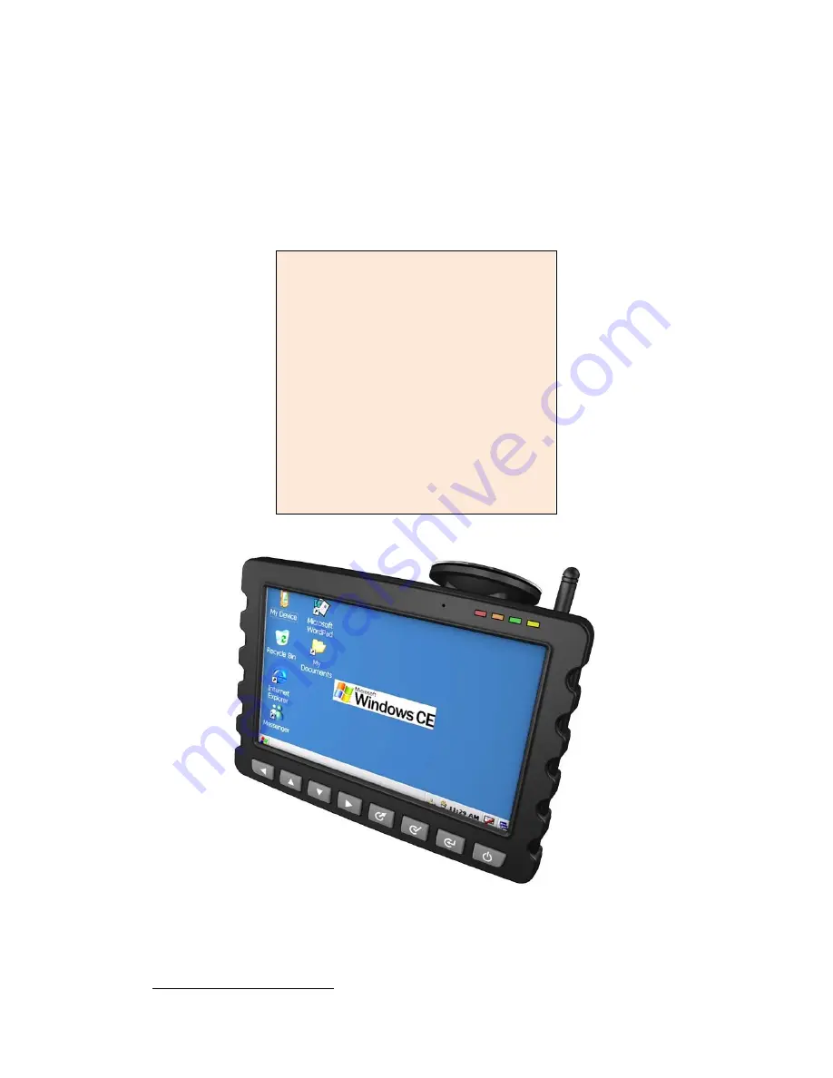
Bolymin BETA903A User Manual Download Page 1

BETA903A 

User Manual 

Features : 

y

 ARM926EJ 

CPU 

y

 7” 

800x480 

TFT 

y

  Host USB x 1 

y

  Device USB x 1 

y

  SD/MMC card port 

y

  2-wire RS232 x 2 

y

  8-wire RS232 x 1   

y

  GPIO x 8 

y

 GPS 


y

 GSM 

y

 Audio 

y

 WinCE 

support 

BOLYMIN, INC.   
13F-1, 20, TA-LONG RD., TAICHUNG CITY 403, TAIWAN, R.O.C.   
WEB SITE:

http://www.bolymin.com.tw

   TEL:+886-4-23293029 FAX:+886-4-23293055 

Summary of Contents for BETA903A

Page 1: ...ost USB x 1 y Device USB x 1 y SD MMC card port y 2 wire RS232 x 2 y 8 wire RS232 x 1 y GPIO x 8 y GPS y GSM y Audio y WinCE support BOLYMIN INC 13F 1 20 TA LONG RD TAICHUNG CITY 403 TAIWAN R O C WEB SITE http www bolymin com tw TEL 886 4 23293029 FAX 886 4 23293055 ...

Page 2: ...BETA903A USER MANUAL 2 History of Version Version Contents Date Note 01 New Version 2010 03 27 SPEC ...

Page 3: ...pecifications of module 18 1 3 2 Mechanical specifications of Holder Mount 19 2 BETA903A Installation guide 20 2 1 Install a sucker mount 21 2 2 Install a GSM antenna 22 2 3 Install a SIM card 23 2 4 Install a SD card 24 2 5 Install external GPS antenna 25 2 6 Install battery 26 2 7 Connect Power 27 2 8 BETA903A power status 28 3 How to test on BETA903A 29 3 1 Serial Port test 30 3 1 1 Connect Ser...

Page 4: ...verview 62 4 3 2 Serial port control CSerialPort class 63 4 3 3 Example code 67 4 4 GSM Control 71 4 4 1 Overview 71 4 4 2 Example code 72 4 5 GPS Message Translator 77 4 5 1 Member functions of class CGPSTranslator 78 4 5 2 Data structure of GPS data 80 4 5 3 Example code 82 4 6 GPIO And Keypad Control 90 4 6 1 How to control GPIO of BETA903A 90 4 6 2 GPIO control functions for BETA903A 91 4 6 3 ...

Page 5: ...USER MANUAL 5 1 General Information This chapter provides basic information of BETA903A module and consists of the following 1 1 Introduction 1 2 Specifications 1 3 Mechanical specifications 1 4 Packing contents ...

Page 6: ...A there are 8 customizable buttons 3 RS 232 1 host USB 1 device USB 4 sets of general purpose I O GPIO Here is the comprehensive product line of BETA903A family Order Information Part No Touch Panel Battery LCD Touch Panel BETA903A 30ɗ 80ɗ BETA903A1ġ 30ɗ 80ɗ 30ɗ 80ɗ BETA903A2 30ɗ 80ɗ BETA903A3 30ɗ 80ɗ 30ɗ 80ɗ BETA903A4 20ɗ 70ɗ BETA903A5 20ɗ 70ɗ 20ɗ 60ɗ BETA903A6 20ɗ 70ɗ BETA903A7 20ɗ 70ɗ 20ɗ 60ɗ 1...

Page 7: ...ndicates BETA903 Status 2 Microphone Supports GSM for voice communication 3 Push Buttons Supports 8 customized menu buttons none system default 1 Status of LED Indicator LED color Description Red Power on Orange Low power Green GPS transmitting signal Yellow GSM receiving signal ...

Page 8: ...Description 4 Speaker For audio replay 5 SIM Card port GSM SIM Card slot 6 Mount holder Fix the module in a car 7 GPS antenna Supports external GPS Antenna One build in GPS supported 8 Battery box Installs optional lithium battery ...

Page 9: ...h Turn on off power 10 Power I O ports Power input炻4x photo coupler input炻4x photo coupler output 11 Serial I 2 wire RS232 x 2 8 wire RS232 x 1 12 Host USB External USB1 0 host for file access 13 Device USB Connect to PC for data sync by using ActiveSync ...

Page 10: ...4 VIO 17 IN1 5 OUT1 18 IN1_GND 6 OUT1_ND 19 IN2 7 OUT2 20 IN2_GND 8 OUT2_GND 21 IN3 9 OUT3 22 IN3_GND 10 OUT3_GND 23 IN4 11 OUT4 24 IN4_GND 12 OUT4_GND 11 Pin assignment for serial I O ports 9 TXD5T 1 GND 10 RXD5T 2 TXD1T 11 RTS5T 3 GND 12 CTS5T 4 RXD1T 13 DTR5T 5 NC 14 DCD5T 6 TXD3T 15 RI5T 7 NC 16 DSR5T 8 RXD3T ...

Page 11: ...BETA903A USER MANUAL 11 Name Description 14 GSM Antenna Connects to GSM 15 SD Card port SD MMC Card slot up to 4GB max Name Description 16 Earphone slot Connects to stereo earphone ...

Page 12: ... 2 1 2 1 Specification System functional blocks NAND FLASH DDR II SRAM ROM SD MMC Card JTAG USB Devic USB Host 2 wire RS232 X 2 8 wire RS232 x 1 Photo coupler IO x 8 Key LCD GSM GPS SPK EAR MIC DC DC Audio codec Charger Battery ...

Page 13: ...8 wire RS232 x1 USB y 1x USB device USB2 0 y 1XUSB host USB1 0 GPIO Supply 4 photo coupler input and 4 photo coupler output Audio y Support DSP based processing stereo codec with SNR 102 dB DAC differential microphone input y Dual channels 2 watts speaker output Integrated Modules y GPS Module LEA 5S y GSM Module SIEMENS MC 55 Supply OS WinCE 5 0 default LCD Size 7 TFT LCD LCD Response 800 x 480 R...

Page 14: ...onomous 1 s 10 s TBD Aided Start 1 s 10 s 10 s Time To First Fix Reacquisition 1 s 10 s TBD Tracking Navigation 160 dBm Acquisition Reacquisition 160 dBm Sensitivity Cold Start Autonomous 145 dBm Autonomous 2 5 m Horizontal Position Accuracy4 SBAS 2 0 m Accuracy of Time pulse Signal RMS 50 ns Max Navigation Update Rate 4 Hz Dynamics 4 g Operational Limits Velocity 515 m s 1000 knots 2 All satellit...

Page 15: ...Frequency Temperature Coefficient 0 20 ppm ɗ Filter LNA Specifications Gain 19 3 Db DC 3 0V Noise Figure 1 5 dB typ DC 3 0V Output V S W R 2 0 max DC 3 0V Current DC 3 0V 0 01V 3 5 1 5 mA Overall Specifications Center Frequency 1575 42 1 023 MHz When covered with a radome on LAN ground plane Gain at Zenith 18 dBi typ for ground 32x8 7 mm Output Impedance 50 ohm Output VSWR 2 0 typ Operation Voltag...

Page 16: ...tion Protocol commonly used for PPP connections y Support of Packet Switched Broadcast Control Channel PBCCH allows you to benefit from enhanced GPRS performance when offered by the network operators CSD data y CSD transmission rates 2 4 4 8 9 6 14 4 kbps non transparent V 110 y Unstructured Supplementary Services Data USSD support SMS y MT MO CB Text and PDU mode y SMS storage SIM card plus 25 SM...

Page 17: ... 6 GSM antenna specifications Parameter Specifications Frequency Range 880 960 MHz and 1710 1990 MHz Impedance 50 ohm VSWR ʀ3 5 Gain 0 dBi Max Polarization Vertical Radiation pattern Near omni directional in the horizontal plane ...

Page 18: ...BETA903A USER MANUAL 18 1 3 1 3 1 Mechanical specifications Mechanical specifications of module ...

Page 19: ...BETA903A USER MANUAL 19 1 3 2 Mechanical specifications of Holder Mount ...

Page 20: ...ide The chapter provides guidance for hardware installation 2 1 Install sucker and mount 2 2 Install GSM Antenna 2 3 Install SIM Card 2 4 Install SD Card 2 5 Install external GPS antenna 2 6 Install battery 2 7 Connect power 2 8 BETA 903A power status ...

Page 21: ... 21 2 1 Install a sucker mount Follow the sequence shown below install BETA903A on the sucker mount and adhere the set onto the front window Carefully choose an appropriate adhering spot such that driving safety is ensured ...

Page 22: ...BETA903A USER MANUAL 22 2 2 Install a GSM antenna Please screw up the antenna into the position as highlighted ...

Page 23: ... USER MANUAL 23 2 3 Install a SIM card Open the SIM Card cover as shown below push left the SIM card holder lever up and place in the SIM card into its fixed position Place the cover into its original position ...

Page 24: ...USER MANUAL 24 2 4 Install a SD card As shown in the following photo plug in the SD card To remove a SD card first make sure the SD is not in the middle of reading process then push on the SD card to release it ...

Page 25: ... BETA903A comes with a build in GPS antenna In case better reception is required users may purchase GPS antenna with MMCX connector as appropriate and connect it the module as indicated Stretch the antenna outside the car or outdoors with clear line of sight ...

Page 26: ...f battery box and remove the cover Then install the battery connector into the socket as indicated and place the battery as appropriate Place the cover back and screw it up to complete the battery installation Note that only a 3 7V 2700mA Lithium battery is applicable and typically with 300 to 350 recharge cycles ...

Page 27: ...connect Pin 3 to a car switch a single throw switch as indicated and the other end of switch to positive end of car battery After power connection is done switch on BETA903A to boot up Switch Fuse Note A quick troubleshooting hint If BETA903A does not boot up as expected please check if the fuse with black housing on the power and I O ports are broken If yes replace them with 5 20mm 1 5A 250V fuse...

Page 28: ...the RTC battery inside BETA903A still supply power to CPU RTC and GPS memory During this mode RTC battery still get slightly charged even for long time no use RTC battery can sustain GPS memory for up to one month If the next power on occurs later than one month it may require more time up to 30 minutes for GPS re positioning to re initialize the GPS memory Note that if GPS positioning always take...

Page 29: ...USER MANUAL 29 3 How to test on BETA903A This chapter provides a step guide to test I O on BETA903A module and it is broken down into 3 1 Serial port test 3 2 GSM test 3 3 GPS test 3 4 GPIO test 3 5 Keypad test ...

Page 30: ...erface to a PC 1st set of 2 wire RS232 Debug Port Via a RS 232 serial cable connect the 1st set to COM port of PC This port is defaulted to a debug port and not for external use Its signal level is at 12 volt 2nd set of 2 wire RS232 COM3 Via a RS 232 serial cable connect the 2nd set to COM port of PC This port is defaulted to COM3 with a signal level of 12 volt ...

Page 31: ...ble serial ports Table of RS232 Pin Assignment RS232 DB9 Connector 1st set of 2 wire RS 232 Debug Port 2nd set of 2 wire RS 232 COM3 8 wire RS 232 COM6 Pin No Pin Name Pin No Pin Name Pin No Pin Name Pin No Pin Name 1 DCD ȹ ȹ ȹ ȹ 14 DCD5T 2 RD 2 RXD1T 6 RXD3T 9 RXD5T 3 TD 4 TXD1T 8 TXD3T 10 TXD5T 4 DTR ȹ ȹ ȹ ȹ 13 DTR5T 5 GND 1 GND 3 GND 3 GND 6 DSR ȹ ȹ ȹ ȹ 16 DSR5T 7 RTS ȹ ȹ ȹ ȹ 12 RTS5T 8 CTS ȹ ȹ...

Page 32: ...mulator to diagnose the communication link Here is the step guide to install hyper terminal at PC end STEP1 Run the hyper terminal on PC then enter BETA903A click on OK STEP2 A Connect to window pops up on Connect using select the applicable COM port click OK To find applicable COM port Click Control panel system hardware device manager COM LPT ports ...

Page 33: ...pops up make sure the bits per second or baud rate and flow control settings match with those on BETA903A A typical baud rate of BETA903A ranges from 9600 to 115200 and use None for flow control Click on Apply then OK Flow control Bits per second baud rate ...

Page 34: ...BETA903A USER MANUAL 34 BETA903A set up STEP1 After booting up BETA903A on Windows CE desktop click on My Device ˤ STEP2 Select Windows folder STEP3 Run SerialPortTest program ...

Page 35: ... running screen STEP5 Please make sure the baud rate setting on PC and BETA903A are identical with a typical range of 9600 to 115200 then clock on Open Port to connect to PC STEP6 Press OK as highlighted Open port BaudRate select Serial port select ...

Page 36: ...7 Enter some trial text message on the TX box then click on Send Tx STEP8 If everything goes fine user will see a receiving message as the one transmitted STEP9 Enter text at PC end those text will be echoed in Rx box at BETA903A ...

Page 37: ...BETA903A USER MANUAL 37 3 2 GSM test Test procedure STEP1 On desktop of Windows CE click on My Device STEP2 Select Windows folder ...

Page 38: ... program STEP4 Running screen of GSMTest STEP5 Before dialing out enter the phone number in the Phone number box tehn click on Dial to make a call Click on Disconnect to hang up Dial out phone no Dial Disconnect Phone number GSM Module Status ...

Page 39: ...BETA903A USER MANUAL 39 STEP6 BETA903A will pop up a screen show a RING at status bar when an incoming call occurs Click on Connect to pick up the phone Click on Disconnect to hang up Connect Disconnect ...

Page 40: ...BETA903A USER MANUAL 40 3 3 GPS test Test Procedure STEP1 On desktop of Windown CE click on My Device ˤ STEP2 Click on Windows folder ...

Page 41: ...BETA903A USER MANUAL 41 STEP3 Run pGPSTest program STEP4 A pGPSTest running screen STEP5 Click on Open GPS to test GPS connectivity ...

Page 42: ...GPS satellite receiving is valid the program will show as follows Data got from GPS module SNR Signal Noise Ratio of Satellite Vehicles SV used to fix position will be marked as blue STEP7 Click on Close GPS to terminate GPS connection ...

Page 43: ...sor and connect IN1 to external voltage with current limiting resistor Rext GI_INPUT1 pin on lower left corner will stay high if switch or sensor is short circuited Among which the GI_INPUT1 is a software defined parameter please refter to chapter 4 6 for details On the other hand GI_INPUT will at its low level if switch or sensor is open BETA903A Note The value of Rext depends on that of Vext The...

Page 44: ...urned on if GO_POUT1 is set to low Among which GO_POUT1 is a software defined parameter please refer to Chapter 4 6 for details On the other hand Device will be turned off if GO_POUT1 is set to high ˤ BETA903A Note The voltage and current value of OUT1 pin depends upon VIO and Rex if any Use caution to keep IIO min current to 5mA and IIO max to 14mA as rated ...

Page 45: ... build in GPIO test program Simply follows the recommended GPIO circuit as illustrated on Chapter 3 4 1 then start using this test program to validate the GPIO ports ˤ Test Procedure STEP1 On desktop of Windows CE click on My Device STEP2 select Windows folder ...

Page 46: ...BETA903A USER MANUAL 46 STEP3 Run GPIO Test_903A program STEP4 A GPIO Test_903A running screen INPUT test items OUTPUT test items ...

Page 47: ...IN1 will be low red colored if the switch shunted on IN1 and IN1_GND is open PIN1 will be high green colored if switch is short ˤ STEP6 OUT1 and OUT1_GND will only be active when POUT1 is checked as highlighted Inactive if otherwise ...

Page 48: ...BETA903A USER MANUAL 48 3 5 Keypad Test BETA903A supports 8 custom defined keypads usu defined as menu buttons Test Procedure STEP1 On desktop of Windows CE click on My Device ...

Page 49: ...BETA903A USER MANUAL 49 STEP2 Select Windows folder STEP3 Run KeyPadTest program ...

Page 50: ...SER MANUAL 50 STEP4 A KeyPadTest running screen STEP5 Keypad test program will indicate green light or high level when keypad is pressed red light or low level if otherwise Keypad Signal Keypad Status Description ...

Page 51: ...ners to get a feel about the development environment using Microsoft Embedded Visual C 4 0 Sample program demonstrates how to control GPS GSM GPIO Keypad and Serial Port through software control 4 1 Transfer File Between BETA903A And PC 4 2 Programming For BETA903A 4 3 Serial Port Function 4 4 GSM Control 4 5 GSM Message 4 6 GPIO and Keypad Control ...

Page 52: ...osoft ActiveSync 4 5 on desktop PC You may download the ActiveSync program from here http www microsoft com downloads details aspx familyid 9e641c34 6f7f 404d a04b dc 09f8141141 displaylang en tm After installation you need to restart PC STEP 2 Connect desktop PC and BETA903A by USB cable The following picture shows the hardware connection between desktop PC and BETA903A for file transfer ...

Page 53: ...stem on PC will request for the USB device driver of BETA903A Please install USB driver as follows 1 Select the advance item on below dialog and click Next button 2 Click Browse button and then select the directory which includes USB device driver file of BETA903A Click Next button Directory which includes USB device driver file of 903A ...

Page 54: ...BETA903A USER MANUAL 54 3 Click Continue button 4 Click Finish button Now BETA903A will connect to PC by ActiveSync ...

Page 55: ...BETA903A USER MANUAL 55 5 Select No and click Next button to cancel the synchronization ...

Page 56: ...lished your ActiveSync application will show a connected status The green circle means the connection between PC and BETA903A is done sucessfully Run Explore program and browse into the folder of BETA903A You can easily transfer files between PC and BETA903A Folder of BETA903A ...

Page 57: ...oaded from http www microsoft com downloads details aspx FamilyID 1DACDB3D 50D1 41B2 A10 7 FA75AE960856 displayLang en 2 Connect BETA903A and Desktop PC by procedures in section 4 1 3 Install SDK of BETA903A provided by Bolymin The installation file could be found in the product CD 4 The platform setting of embedded Visual C Following pictures show the necessary setting of eVC 4 0 BETA903A device ...

Page 58: ...n we will show you how to create a new project in eVC 4 0 You may skip this section if you are already familiar with WinCE development environment You could create a new project for your application as follows STEP 1 Execute eVC 4 0 STEP 2 Select File New function ...

Page 59: ...n type set up the location and name of your project and Please select WCE MFC AppWizard exe as application type Project name Project location STEP 4 Select Dialog based and language setting Click Next button Application type Only select ARMV4I as CPU type ...

Page 60: ...BETA903A USER MANUAL 60 STEP 5 Click Next button STEP 6 Click Next button ...

Page 61: ... 61 STEP 7 Click Finish button STEP 8 Now you can add your codes into this new project For learn more about WinCE development environment please explore the MSDN website http msdn microsoft com en us library bb847963 aspx ...

Page 62: ... Below table lists the function of each serial port Name Function Comment COM1 GSM control port Detail information could be found in section 4 4 COM4 GPS control port Detail information could be found in section 4 5 COM3 Used by application program 2 wire RS232 COM6 Used by application program 8 wire RS232 Debug port For internal use only Can not be opened by application program ...

Page 63: ...ject Customer could modify the source code of class CSerialPort to expand the serial port functions 4 3 2 1 Basic concept of class CSerialPort The CSerialPort object class will handle all data transfer and receiver of opened serial port Once any data is received by the opened serial port CSerialPort object will send a user defined message to user defined window which should be main window of appli...

Page 64: ...ARITY Return value TRUE Open serial port successfully FALSE Open serial port fail Send Function Send specific data by this serial port Syntax BOOL Send LPCVOID buf_ptr DWORD data_len Parameters buf_ptr Memory pointer of data will be sent data_ len Length of data will be sent UNIT byte Return value TRUE Send data successful FALSE Send data fail SetCommMsg Function CSerialPort object will send a rec...

Page 65: ...BETA903A USER MANUAL 65 Close Function Close current serial port Syntax BOOL Close Parameters None Return value TRUE Close serial port successfully FALSE Cloas serial port fail ...

Page 66: ...ived message as follows STEP 1 Define a receive message in your code as below const UINT WM_CMD_OK WM_USER 1 STEP 2 Declare a message processing function in the window that will process receive message STEP 3 Create message mapping STEP 4 Implement the receive message processing function ...

Page 67: ...des of the test program is shown below File SerialPortDlg cpp CSerialPortDlg dialog const UINT WM_CMD_OK WM_USER 1 BEGIN_MESSAGE_MAP CSerialPortDlg CDialog AFX_MSG_MAP CSerialPortDlg ON_BN_CLICKED IDC_OPEN_COM OnOpenCom ON_BN_CLICKED IDC_CLOSE_COM OnCloseCom ON_BN_CLICKED IDC_SEND OnSend ON_BN_CLICKED IDC_CLEAR_SEND OnClearSend ON_BN_CLICKED IDC_CLEAR_REC OnClearRec ON_WM_DESTROY AFX_MSG_MAP ON_ME...

Page 68: ...fine searial port COM1 m_ComboStop SetCurSel 0 Define stop bit 1bit m_ButClose EnableWindow FALSE Close Button is disable m_strRecDisp _T m_cSendBuffer new char 60 UpdateData FALSE m_pSerialPort new CSerialPort m_pSerialPort SetCommMsg m_hWnd WM_CMD_OK return TRUE Create a CSerialPort object and set current window as the window which will process received data Implement function used to process re...

Page 69: ... button used to open selected serial port void CSerialPortDlg OnOpenCom UpdateData TRUE CString strPort PorTbl m_ComboPort GetCurSel DWORD baud BaudTbl m_ComboBaud GetCurSel DWORD databit DataBitTbl m_ComboData GetCurSel BYTE stopbit StopBitTbl m_ComboStop GetCurSel BYTE parity ParityTbl m_ComboParity GetCurSel BOOL ret m_pSerialPort Open strPort baud databit stopbit parity if ret FALSE Open selec...

Page 70: ...rtDlg OnSend UpdateData TRUE int len m_strSendEdit GetLength for int i 0 i len i m_cSendBuffer i char m_strSendEdit GetAt i BOOL status m_pSerialPort Send m_cSendBuffer len if status MessageBox _T Can t write string to COM _T Error MB_OK Destory function of serial port test dialog void CSerialPortDlg OnDestroy CDialog OnDestroy m_pSerialPort Close delete m_pSerialPort Close current serial port Sen...

Page 71: ... AT command to control the GSM module Here is some AT commands used in our example application AT command Description ATA Answer a call ATH Disconnect existing call ATD n Set up an outgoing call n phone number AT SNFS n Set the audio mode required for the connected equipment The audio mode should be set to 2 for GSM module of BETA903A More detailed description about AT command could be found at do...

Page 72: ...ne number will be dialed The button will be activated while receive RING message Click this button to answer the phone Dial by input phone number Below are the major source codes of the test program File pGSMTestDlg cpp const UINT WM_CMD_REVMSG WM_USER 1 BEGIN_MESSAGE_MAP CPGSMTestDlg CDialog AFX_MSG_MAP CPGSMTestDlg ON_WM_CLOSE ON_BN_CLICKED IDC_BTN_CONNECT OnBtnConnect ON_BN_CLICKED IDC_BTN_DISC...

Page 73: ...ow is not a dialog SetIcon m_hIcon TRUE Set big icon SetIcon m_hIcon FALSE Set small icon CenterWindow GetDesktopWindow center to the hpc screen m_cSendBuffer new char 60 m_pSerialPort new CSerialPort m_pSerialPort SetCommMsg m_hWnd WM_CMD_OK if m_pSerialPort Open _T COM1 57600 8 ONESTOPBIT NOPARITY m_strStatus _T Open COM error m_btnDial EnableWindow FALSE Disable Dial button UpdateData FALSE ret...

Page 74: ...put return TRUE return TRUE unless you set the focus to a control void CPGSMTestDlg OnClose delete m_pSerialPort delete m_cSendBuffer m_pSetGPOutput NULL FreeLibrary m_hModule CDialog OnClose Implement function used to process receive data from serial port LRESULT CPGSMTestDlg OnCommRecv WPARAM wParam LPARAM lParam char buf DWORD buflen CString tmp buf char wParam buflen DWORD lParam m_strStatus _...

Page 75: ...lse if m_strStatus Find _T RING 1 m_btnConnect EnableWindow TRUE Enable Connect button else if m_strStatus Find _T NO CARRIER 1 m_pSetGPOutput GO_AMP_SWITCH FALSE Switch amplifier to audio Set the audio mode of GSM module to 2 m_btnDisConnect EnableWindow FALSE Disable DisConnect button m_btnConnect EnableWindow FALSE Disable Connect button UpdateData FALSE return 0 void CPGSMTestDlg OnBtnConnect ...

Page 76: ...tring temp_str UpdateData TRUE temp_str Format _T ATD s r m_strPhone SendATCmd temp_str Hang up current call and switch amplifier to audio Setup a call by input phone number m_bConnectCall TRUE m_btnDisConnect EnableWindow TRUE Enable DisConnect button void CPGSMTestDlg OnTimer UINT nIDEvent m_pSetGPOutput GO_AMP_SWITCH TRUE m_bConnectCall FALSE Switch amplifier to GSM function m_btnConnect Enable...

Page 77: ...ud rate 9600 Data bit 8 Stop bit 1 No parity User application could receive GPS messages by CSerialPort object and translate GPS messages by object of class CGPSTranslator provided by Bolymin Application can use this class by adding CGPSTranslator cpp and CGPSTranslator h into project CGPSTranslator will translate messages from GPS module into related data structure described in section 4 5 2 ...

Page 78: ...osition fixed Syntax BOOL IsGPSFixed Parameters None Return value TRUE GPS position fixed FALSE GPS position not fixed GetGSVData Function Get data of the last translated GSV message Syntax void GetGSVData stGSVData data_ptr Parameters data_ptr memory pointer of GSV data Return value None GetVTGData Function Get data of the last translated VTG message Syntax void GetVTGData stVTGData data_ptr Para...

Page 79: ... GLL data Return value None GetGGAData Function Get data of the last translated GGA message Syntax void GetGGAData stGGAData data_ptr Parameters data_ptr memory pointer of GGA data Return value None GetRMCData Function Get data of the last translated RMC message Syntax void GetRMCData stRMCData data_ptr Parameters data_ptr memory pointer of RMC data Return value None ...

Page 80: ...ial E Estimated N Data not valid Data structure stVTGData Data type Data name Description double dCourseDegree True course made good over ground by degree char cCourseIndicator Course indicator double dMagneticDegree Magnetic course made good over ground by degrees char cMagneticIndicator Magnetic indicator double dGroundSpeedInKnots Speed over ground in knots char cGroundSpeedUintKno t Unit of pr...

Page 81: ...mss ss char cDataValid Data status A valid data Data structure stGSAData Data type Data name Description char cMode Mode M Manual forced to operate in 2D or 3D A Automatic 3D 2D int iModeValue Mode value 1 Fix not available 2 2D 3 3D int iPRN 12 PRN of Satellite Vechicles SV s used in position fix 0 for unused field double dPDOP Position Dilution of Precision PDOP double dHDOP Horizontal Dilution ...

Page 82: ...ived GPS message will be displayed here Click Show GPS message check box to ON OFF the GPS message display Click Clear message button to clear all message here Below are the major source codes of the test program File pGPSTestDlg cpp const UINT WM_CMD_REVMSG WM_USER 1 CPGPSTestDlg dialog BEGIN_MESSAGE_MAP CPGPSTestDlg CDialog AFX_MSG_MAP CPGPSTestDlg ON_WM_CLOSE ON_WM_TIMER ON_WM_PAINT ON_BN_CLICK...

Page 83: ...Port SetCommMsg m_hWnd WM_CMD_REVMSG m_bOpenGPS FALSE m_pGPSTranslator new CGPSTranslator m_iCurBufIndex 0 Create object of CGPSTranslator m_bShowMsg FALSE m_pstrSV_PRN 0 m_strSV_PRN1 m_pstrSV_PRN 1 m_strSV_PRN2 m_pstrSV_PRN 2 m_strSV_PRN3 m_pstrSV_PRN 3 m_strSV_PRN4 m_pstrSV_PRN 4 m_strSV_PRN5 m_pstrSV_PRN 5 m_strSV_PRN6 m_pstrSV_PRN 6 m_strSV_PRN7 m_pstrSV_PRN 7 m_strSV_PRN8 m_pstrSV_PRN 8 m_str...

Page 84: ...stDlg OnBtnOpengps if m_bOpenGPS Close GPS if m_pSerialPort Close m_strGPSMsg _T Close GPS OK r n KillTimer 1 m_btnOpenGPS SetWindowText _T OpenGPS m_bOpenGPS m_bOpenGPS else m_strGPSMsg _T Close GPS Fail r n else OpenGPS if m_pSerialPort Open _T COM4 9600 8 ONESTOPBIT NOPARITY Open COM4 to communicate with GPS module m_strGPSMsg _T Open GPS OK r n SetTimer 1 1000 NULL m_btnOpenGPS SetWindowText _...

Page 85: ...ss receive data from serial port LRESULT CPGPSTestDlg OnCommRecv WPARAM wParam LPARAM lParam CString tmp char buf DWORD buflen int i buf char wParam buflen DWORD lParam if m_bShowMsg for i 0 i buflen i buf tmp Format _T c buf m_strGPSMsg tmp UpdateData FALSE Catch a complete GPS message Start with end by ignore checksum i 0 while buflen 0 if m_iCurBufIndex 0 message start find ...

Page 86: ...rBufIndex Send current received message to GPSTranslator m_iCurBufIndex 0 i buflen return 0 void CPGPSTestDlg OnTimer UINT nIDEvent UpdateScreen CDialog OnTimer nIDEvent Implement function used to display current GPS data void CPGPSTestDlg UpdateScreen stRMCData data_RMC stGSAData data_GSA stGGAData data_GGA stVTGData data_VTG stGSVData data_GSV Variables used to get current GPS data ...

Page 87: ...rAltitude Format _T 1f 0 0 m_strSpeed Format _T 1f 0 0 m_strPDOP Format _T d 0 m_strHDOP Format _T d 0 m_strVDOP Format _T d 0 else t mp_int 0 int data_RMC dLatitude 100 tmp_int 1 int data_RMC dLatitude tmp_int 0 100 tmp_double data_RMC dLatitude tmp_int 0 100 tmp_int 1 60 m_strLatitude Format _T c dd d 1f data_RMC cLatitudeNS tmp_int 0 tmp_int 1 tmp_double tmp_int 0 int data_RMC dLongitude 100 tm...

Page 88: ...dGroundSpeedInKM Update SV status CRect rect m_pGPSTranslator GetGSVData data_GSV for int i 0 i 12 i Get current GGA data Get current VTG data Get current GSV data if data_GSV SVData i iPRN 0 m_pstrSV_PRN i Format _T d data_GSV SVData i iPRN m_pstSV_SNR i GetWindowRect rect ScreenToClient rect InvalidateRect rect else m_pstrSV_PRN i Format _T c UpdateData FALSE Check if the input SV was used for p...

Page 89: ... 12 i m_pstSV_SNR i GetWindowRect rect ScreenToClient rect if data_GSV SVData i iSNR 100 data_GSV SVData i iSNR 0 tmp_str Format _T d data_GSV SVData i iSNR else tmp_str _T rect right rect left rect Width 100 data_GSV SVData i iSNR if IsFixedSV data_GSV SVData i iPRN data_GSA bar_color RGB 0 0 255 else bar_color RGB 255 0 0 dc FillSolidRect rect bar_color src_color dc SetBkColor bar_color dc SetTe...

Page 90: ...dlibrary function STEP 3 Get the address of control functions by GetProcAddress function STEP 4 Execute GPIO control functions by the address got at STEP3 Here is a simple example code to use the GPIO control functions variable declaration HINSTANCE m_hModule BOOL m_pGetGPInput int void m_pSetGPOutput int BOOL m_hModule LoadLibrary _T pGPIO_903A dll m_pGetGPInput BOOL int GetProcAddress m_hModule ...

Page 91: ...efinition Return value TRUE Current status of specified GPIO is HIGH FALSE Current status of specified GPIO is LOW SetGPOutputFunction Set value of specified GP Output Syntax void GetGPOutput int gpio_index BOOL value Parameters gpio_index The index of specified GP output Refer to section 4 6 3 for the value definition Value New value of specified GP output TRUE Set specified GP output to HIGH FAL...

Page 92: ... defined general purpose output OUT1 GO_POUT2 User defined general purpose output OUT2 GO_POUT3 User defined general purpose output OUT3 GO_POUT4 User defined general purpose output OUT4 GO_BLIGHT_ENABLE Backlight control Default value HIGH GO_LCD_POWER_ENABLE LCD power control Default value LOW GO_EARPHONE_SWITCH Earphone switch Default value HIGH Set LOW when earphone is used for GSM function GO...

Page 93: ...essed you may catch WM_KEYDOWN or WM_KEYUP message in your program and add the process codes Here is a step guide STEP 1 Override PreTranslateMessage function of the window which will catch key message as shown below STEP 2 In Class view of eVC 4 0 click right button of mouse on the window that will catch the key message Select Add Windows Message Handler and then select WM_KEYDOWN or WM_KEYUP mes...

Page 94: ...BETA903A USER MANUAL 94 STEP 3 Add process code into message processing function ...

Page 95: ...BETA903A USER MANUAL 95 End of BETA903A User Manual ...

Reviews: