ENGLISH
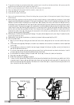
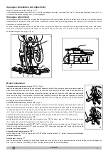
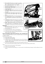
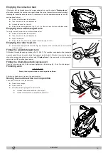
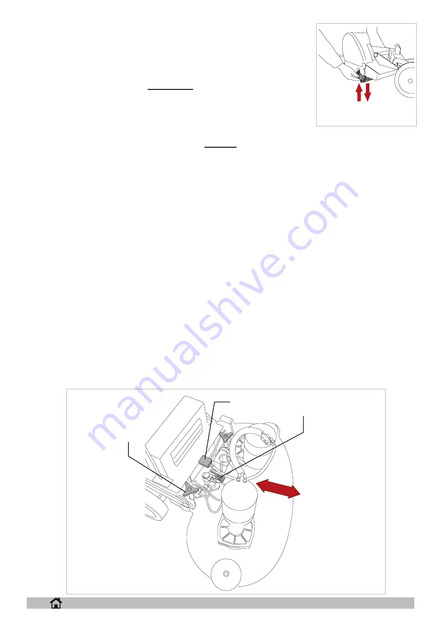
Attaching the brush roller
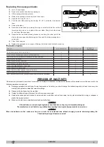
(Fig. 23):
raise the machine head by pushing the head lift pedal down and then to the left,
fit the rollers in their housing by
first inserting them on the drive pulley, then pushing them upwards until they click into place.
Releasing the brush roller
(Fig. 23):
raise the machine head by pushing the head lift pedal down and then to the left,
release the rollers by pulling
them downwards from the side opposite the drive pulley, then extracting them from their housing.
! INFORMATION
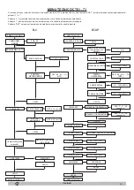
Follow the instructions given below to configure the machine’s control software to use the display
language you require:
See the “
Technical menu
” section.
Lifting and transporting the machine
! WARNING
All phases of lifting and moving must be performed in an adequately illuminated environment with the adoption of the safety measures
most appropriate to the situation.
The operator must always use personal protection devices.
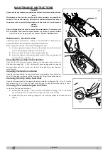
Proceed as follows to load the machine onto a means of transport:
►
Empty the tanks.
►
Remove the batteries.
►
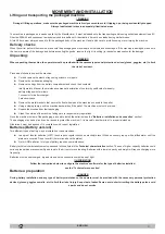
Push the machine onto the pallet using a sloping ramp, securing the front wheels and the chassis using the brackets supplied. The machine
must not be raised.
►
Lift the pallet (with the machine) using a fork lift truck and load it onto the means of transport.
►
Anchor the machine to the means of transport with cables connected to the pallet and to the machine itself.
Quick head change (BATTERY POWERED VERSIONS ONLY)
The scrubber head can be changed as described below.
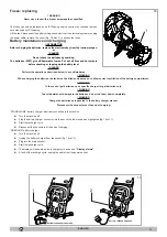
Removing the head:
►
Lower the head (mechanical version) or select “CHANGE HEAD” (electronic version) in the “
Technical menu
”, pressing the “+” or “-” button
raises or lowers the head, releasing the button stops the actuator. Pressing the “SET” button exits the page and the machine lifts the head.
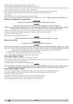
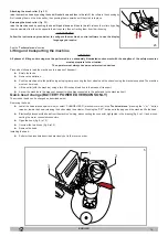
► Electrically disconnect the head from the machine’s wiring, disconnecting the connector highlighted in the drawing (fig. 5-ref. 1) and discon
-
necting the motor connector/connectors.
► Open the hook (fig. 5, ref. 2).
► Unscrew the two knobs (fig. 5-ref. 3).
►
Remove the head.
Installing the head:
►
Perform the procedure described previously but in the reverse order.
1
2
3
5
23
14
Summary of Contents for 6 BT 70
Page 71: ......

