19
DSP features and controls are described in the following table.
The DSP features that can be applied to a channel, accessible through the DSP Features
menu, are described in the following table.
Note:
The DSP page (including the mixing board and other DSP pages) can only be
used by one browser session at a time. If another session is already connected and
using this DSP page, the mixing board displayed will be disabled.
Note:
If two output connectors are configured for Bridge mode (A/B), the output chan
-
nel that corresponds to the second connector (B) will not appear on the mixing board
interface.
Table 8. DSP Page
Save Settings to Server
Backs up the DSP settings to the server. If this device is
later replaced or reset to factory defaults, these DSP set
-
tings can be restored when the new device is “swapped”
for the old on the Nyquist server.
Note:
This button appears on each DSP feature page.
Mute
Silences the audio for the selected channel.
DSP Features button
Presents a menu of DSP features that can be applied to the
corresponding channel.
Level Slider
Adjusts the channel volume level in 1–dB increments.
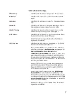
NET-IN LED
Illuminates when a signal is being received from the Net
-
work stream input.
LINE-IN LED
Illuminates when a signal is being received from the ana
-
log Line input.
Clip LED
Illuminates when a signal has exceeded the maximum
threshold, indicating that the signal is “clipping.”
IN VU meter
Indicates the strength of the input signal.
OUT VU meter
Indicates the strength of the output signal.
Pink Noise
When set to ON, a pink noise signal will be sent to the out
-
put channel.
Phase Invert
When set to ON, the signal for this channel is inverted,
usually to prevent two similar but out-of-phase signals
from canceling each other out.


