

Page 8
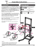
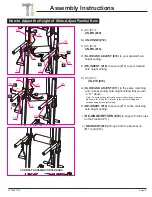
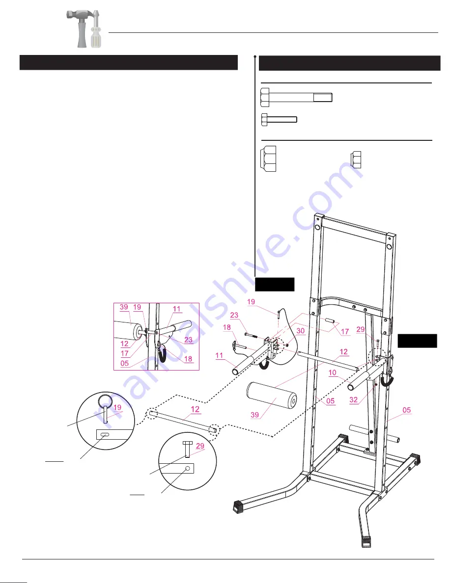
With the help of an assistant, attach the
Right VKR Parallel Bar (#11)
to the
Right Upright (#05)
; secure them together by using one
Pop-pin (#18)
inserted through lower hole of the bracket on
Right VKR
Parallel Bar (#11)
and top hole on
Right Upright (#05).
Next, continue
securing them together by using one
Hex Bolt (#23)
inserted through
upper hole of the bracket on
Right VKR Parallel Bar (#11),
one
Bushing (#17),
the other side of the bracket on
Right VKR Parallel
Bar (#11)
and secure with one
Nylon Nut (#30).
Repeat this process on the other side.
Slide on the
Foam Roller (#39)
onto the
Foam Roller Tube (#1
2
)
.
Insert the
Foam Roller Tube (#12)
into the two small brackets on the
Left VKR Parallel Bar (#10)
and
Right VKR Parallel Bar (#11).
(Please ensure that the CIRCLE-shaped hole is on the left side,
and the OVAL-shaped hole is on the right side.)
On the left side (CIRCLE-shaped hole), secure using one
Hex Bolt
(#29)
and one
Nylon Nut (#32)
.
NOTE: Please do not over-tigthen the
Hex Bolt (#29)
so that it is
easier for you to slide-adjust the height.
On the right side (OVAL-shaped hole), secure by inserting one
Pop-pin (#19).
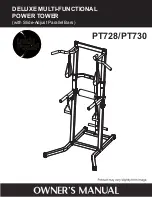
PT728/PT730
NOTE:
For easier assembly, only hand-tighten the Nuts
& Bolts for now. After all parts have been put in
place, then proceed to tighten with a wrench.
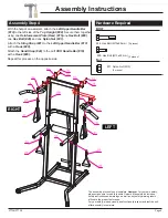
Assembly Step 3
Hardware Required
Assembly Instructions
RIGHT
(RIGHT Side:
OVAL
-shaped hole)
(LEFT Side:
CIRCLE
-shaped hole)
Pop-pin (#19)
Nylon Nut (#32)
LEFT
Nut
BOLT
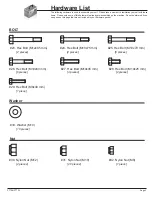
#23. Hex Bolt (M12x85 mm)
[2 pieces]
#29. Hex Bolt (M8x40 mm)
[1 piece]
#30. Nylon Nut (M12)
[2 pieces]
#32. Nylon Nut (M8)
[1 piece]
(VIEW OF CORRECTLY ASSEMBLED
RIGHT
SIDE FROM
REAR
PERSPECTIVE)


