


Assembly Instructions
Page 10
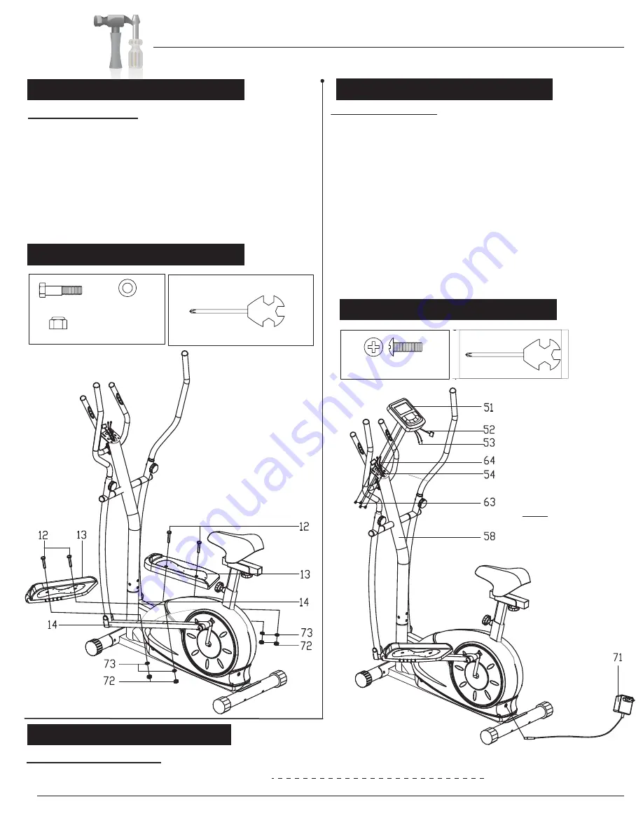
PEDAL ASSEMBLY
A s s e m b l y S t e p 7
After complete assembly: If the computer is
not picking up your hand pulse signal
(or you are getting
inaccurate readings), Please refer to our “Troubleshooting” section on
Page 1
6
for other troubleshoot issues.
HAND PULSE SIGNAL
Hardware / Tool Required
Hardware / Tool Required
#63. Screw (M4 x 10mm)
[4 pieces]
A s s e m b l y S t e p 8
#12. Bolt (M8x45 mm)
[4 pieces]
#73. Washer
[4 pieces]
#72. Nylon Nut
[4 pieces]
Attach the two Pedals (#13) as shown using a
total of four Bolts (#12), four Washers (#73)
and four Nylon Nuts (#72). The pedals are
marked with "L" or "R". Make sure the pedals
are positioned as shown otherwise they
will not fit properl
y
. If the pedals do not fit,
make sure that you installed the Spacer (#31)
correctly during step number 3.
Troubleshooting
BRM3671/3681/3690
COMPUTER ASSEMBLY
Remove the Screws (#63) that are pre-assembled on the Computer
(#51) and set them aside for now. Connect the Main Sensor Wire
(Middle) (#54) to the Main Sensor Wire (Upper) (#52). Then, connect
the Pulse Sensor Wire (Lower) (#64) to the Pulse Sensor Wire (Upper)
(#53). Attach the Computer (#51) to the bracket on the Center Post
(#58) by using the four Screws (#63) that were previously removed.
Plug in the AC Adapter (#71) male plug into the female socket
located at the rear of the unit.
The assembly process is now complete. However, for your own safety,
please make sure to read this entire Owner’s Manual which includes
safety instructions and warnings, as well as any safety/warning labels
affixed to the product before use.
For your safety, please visually and functionally inspect and test the unit
after assembly is complete.
Note: This power unit is
intended to be correctly
orientated in a vertical or
floor mount position.


