


Page
8
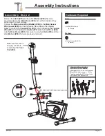
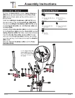
Assembly Instructions
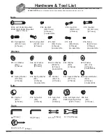
Hardware Required
#45. Carriage Bolt
(M8×40 mm)
[4 Pieces]
#51. Bolt
(M8×30 mm)
[2 Pieces]
#52. Spring Washer
(M8)
[2 Pieces]
#44. Arc Washer.
(M8, R16)
[4 Pieces]
#58. Nut (M8)
[4 Pieces]
Bolts
Washers
Nuts
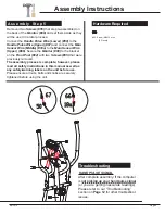
A s s e m b l y S t e p 4
Insert the
Left/Right Handlebars (#07L/07R)
onto
the open ends of the two
Coupler Bars (#06L/06R).
Secure the
Left/Right Handlebars (#07L/07R)
using
two
Carriage Bolts (#45)
, two
Arc Washers (#44)
and
Nuts (#58).
Install the
Pulse Handle Bar (#08)
onto the front side
of the
Front Post (#02)
using two
Bolts (#51)
and two
Spring Washers (#52)
that were previously removed.
Slide the
Cover of Handlebar (#53)
over the
Pulse
Handlebar (#08).
Feed the
Handle Pulse Wire (Lower) (#50)
through
the neck of the
Front Post (#02)
until they are sticking
out of the opening.
You’ll need to connect the
Monitor
(#09)
Later.
Remove
two
Bolts (#51)
and two
Spring Washers
(#52)
that were pre-assembled on the
Front Post
(#02)
and set them aside as they will be used in a
later process.
two
Feed the
Handle Pulse Wire
(Lower) (#50)
through the
neck of the
Front Post (#02)
until they are sticking out of
the opening.
0
7
0
3
R
B