background image


Page 29


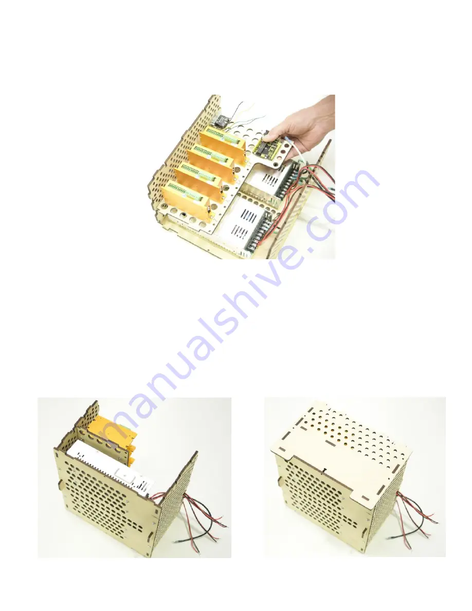
Align the tabs on the C6 Driver/UNO Shelf to the C1 
Front Panel into the corresponding slots and carefully 
slide into place.


Turn the Controller Box with the left side down. Align 
the tabs and slots of the C4 Right Side Panel, Drive Shelf 
and Bottom Plate and slide into place, then secure with 
five M4 x 16 Machine Screws and Nuts


Step 6.3


Step 6.2


Summary of Contents for KL7 Series

Page 1: ...Page 1 Controller Assembly Manual KL 7 Series MANUAL 6 of 8 Version 2 1...

Page 2: ...Supply Wires 19 24 Front Panel Assembly with Emergency Hold Resume Switches 25 26 Attaching Power Switch to Left Side Panel 27 Controller Encloser Assembly 28 30 Connecting Power and Emergency Stop S...

Page 3: ...s warning CAUTION Indicates a serious risk of bodily harm possible injury and death This warning box is to be taken seriously Any work must be carried out with extreme caution Please review each assem...

Page 4: ...Page 4 Please refer to the 24 x 18 Controller Wiring Diagram enclosed with your KL7 series CNC Router Kit...

Page 5: ...age 5 Parts for assembly include Wood Components Parts List Part Description Qt y Photo C1 Front Panel 1 C2 Back Panel 1 C3 Wire Clamp 1 C4 Right Side Panel 1 C5 Left Side Panel 1 C6 Driver Uno Shelf...

Page 6: ...Page 6 Part Description Qt y Photo C7 Bottom Plate 1 C8 Top Plate 1...

Page 7: ...Machine Screws 40 H15 M4 Nuts 40 H27 M2 5 x 16 Machine Screws 6 H28 M2 5 x 16 Nuts 6 H29 3mm Spacer 4 H30 8mm Spacer 8 E1 KL 350 148 110V AC 48V DC Power Supply 2 E2 24 V Servo Driver 4 E3 Uno 1 E4 Un...

Page 8: ...rk fork 1 E13 14 Green 140mm AC Ground Wire fork female 1 E14 14 Black 210mm fork fork 1 E15 22 White 320mm 22 Purple 320mm 1 ea E16 18 Black Red 350mm DC Power Wires 4 E17 22 Orange 250mm 22 Blue 250...

Page 9: ...Page 9 Part Description Qty Photo E25 22 Black 40mm Jumpers 8 E26 22 Brown Blue 80 mm 1 ea E27 Power Cord 1...

Page 10: ...he Bottom Plate for each Power Supply as shown Step 1 1 Make certain the Power Supply Selector Switch is set to 110V as seen below Failure to do so will negatively affect machine performance CAUTION S...

Page 11: ...r s tape to hold the Machine Screws temporarily in place as shown below Step 1 3 Gently rotate the Back Plate so the Machine Screw threads are visible Slip a 8mm Spacer over each of the four of the Sc...

Page 12: ...5 Apply light pressure to hold the Power Supply and Screws together and gently turn the Bottom Plate and Power Supply over Spacers are used to create an air space to facilitates air flow around each...

Page 13: ...n securely with a Phillips head screwdriver repeat for until all four M4 X 16 Machine Screws are secure Be sure the spacers remain in place Repeat the process to secure the second Power Supply to the...

Page 14: ...thread an M4 nut on each Screw as shown below Step 2 1 Make certain the 1 and 4 DIP Dual In Line Package Switches are set as shown If the switches are not set correctly the Servo Motors will not opera...

Page 15: ...Z Elevate the Screw head and slip the Drive base slot around the Screw Then holding Base snug against the Screw insert a M4 x 16 Screw through the opposite end and secure with a Nut Tighten both Nuts...

Page 16: ...pacers above each of the mounting holes on the UNO Template as shown Gently orient the mounting hole of the UNO Board over the Spacers and place one M2 5 x 16 Machine Screw through each of the four mo...

Page 17: ...ge 17 Hold Screw heads in place with pieces of blue painter s tape Thread a M2 5 Nut onto each of the Screws and secure Do not over tighten the Screws and Nuts to protect the UNO board Step 2 7 Step 2...

Page 18: ...Page 18 The completed installation is shown below The orientation of the Servo Drivers and the Micro Controllers is important...

Page 19: ...t all electrical power when servicing power supply controller or drivers DANGER It is essential that every wire connection is made correctly Incorrect wiring may result in machine and or component fai...

Page 20: ...Page 20 Connect the 14 Green 140 mm AC Ground Wire fork female to earth ground on Power Supply as shown Step 3 1 NOTE The female connector will be connected in a later step...

Page 21: ...minals using the 14 White 210mm AC Neutral Wire fork fork as shown Add 14 White 140mm AC Neutral Wire fork female to the neutral terminal on Power Supply as shown Step 3 3 NOTE The female connector wi...

Page 22: ...rminals using the 14 Black 210mm AC Power Wire fork fork as shown Connect the 14 Black 440mm AC Power Wire fork fork to load terminal on Power Supply as shown Step 3 5 NOTE The forked terminal will be...

Page 23: ...ground wire must be routed neatly beneath the AC wires as shown below Connect a 22 Black 130 mm wire to the Power Supply V DC ground terminal as shown below NOTE The free end of this wire will be conn...

Page 24: ...e black wires to the V as shown There are two sets of wires for each Power Supply Attach the 18 Black Red 350 mm wires to the second Power Supply as shown Note the red wires to V and the black wires t...

Page 25: ...t the mounting screws until the end of the screw is flush with the base Step 4 1 Place the red button through the large hole in the C1 Front Panel as shown terminal block on top and reattach the twist...

Page 26: ...back of the button switch Insert the switch wires and the threaded base through the hole marked Hold on the front panel and secure by firmly reattaching the plastic nut Step 4 3 Repeat steps to attac...

Page 27: ...e Power Switch to the Left Side Panel and secure with two M2 5 x 16 Screws and Nuts Step 5 0 NOTE Make sure the switch is on the top with the receptacle on the bottom as shown Attaching Power Switch t...

Page 28: ...with two M4 x 16 Machine Screws and Nuts as shown Attach the C2 Back Panel to the C7 Bottom Plate and secure with two M4 x 16 Machine Screws and Nuts as shown Step 6 0 NOTE The Back Panel wire cutout...

Page 29: ...the corresponding slots and carefully slide into place Turn the Controller Box with the left side down Align the tabs and slots of the C4 Right Side Panel Drive Shelf and Bottom Plate and slide into p...

Page 30: ...Page 30 Repeat the process to attach the C5 Left Side Panel to the Back Panel and Bottom Plate and secure with five M4 x 16 Machine Screws and Nuts as shown below Step 6 4...

Page 31: ...140mm AC Neutral Female end to Power Supply Switch right side blade as shown Step 7 1 Connect the 14 Black 440mm AC Power wire Female end to Power Supply Switch right side blade as shown NOTE this wi...

Page 32: ...4 Black 440 mm AC forked connector from the Power Switch to the Emergency Stop Terminal Block as shown Step 7 4 Step 7 5 Attach 14 Black 440 mm AC forked connector on the Power Supply to the terminal...

Page 33: ...Page 33 Secure the 14 black wires to the Back Panel with two Zip Ties and shown below Step 7 7 ZIP ties...

Page 34: ...e pins of the Screw Shield into the UNO Controller sockets ensuring the rearward pins and sockets match as shown Step 8 0 Installing Screw Shield and Connecting Control Wires Align rearward pins and s...

Page 35: ...Page 35 Attach 22 Black 130 mm DC Ground Wire from the Power Supply to the GND on the Screw Shield as shown below Step 8 1...

Page 36: ...s connect driver pins 2 and 4 as shown Step 8 3 Using the 22 black 40mm jumpers connect driver pins 4 and 8 as shown Step 8 4 Insert one 22 black 80mm jumper in pin number 8 as shown NOTE The other en...

Page 37: ...Page 37 Repeat for all four Drivers as shown Step 8 5...

Page 38: ...6 Attach the two black Home and Resume Switch wires to the GND terminal as shown Attach the Yellow Hold wire to the number 5 A1 Screw Shield terminal and the Green Resume wire to the number 4 A2 term...

Page 39: ...Page 39 Daisy chain the four Drivers using the 22 red 80mm wires by connecting to the number 7 screw terminal ALM as shown below Step 8 7...

Page 40: ...Page 40 Step 8 8 Connect the 22 red 180mm alarm wire with the ferrite coil to the number 7 screw terminal of the X1 Driver Connect the other end to the A0 Terminal on the Screw Shield as shown...

Page 41: ...Page 41 Step 8 9 Attach the 22 Green 160mm wire from the number 1 PL screw terminal on the X1 driver to the D2 terminal on the Screw Shield as shown X1 Driver...

Page 42: ...Page 42 Attach the 22 Brown 160mm wire from the number 1 PL screw terminal on the X2 driver to the A4 terminal on the Screw Shield as shown Step 8 10 X2 Driver...

Page 43: ...Page 43 Attach the 22 Orange 250mmwire from the number 1 PL screw terminal on the Y Driver to the D3 terminal on the Screw Shield as shown Step 8 11 Y Driver...

Page 44: ...Page 44 Attach the 22 White 320mm wire from the number 1 PL screw terminal on the Z Driver to the D4 terminal on the Screw Shield as shown Step 8 12 Z Driver...

Page 45: ...Page 45 Attach the 22 Yellow 160mm wire from the number 3 DIR screw terminal on the X1 Driver to the D5 terminal on the Screw Shield as shown Step 8 13 X1 Driver...

Page 46: ...Page 46 Attach the 22 Gray 160mm wire from the number 3 DIR screw terminal on the X2 Driver to the A3 terminal on the Screw Shield as shown Step 8 14 X2 Driver...

Page 47: ...Page 47 Attach the 22 Blue 250mm wire from the number 3 DIR screw terminal on the Y Driver to the D6 terminal on the Screw Shield as shown Step 8 15 Y Driver...

Page 48: ...Page 48 Attach the 22 Purple 320mm wire from the number 3 DIR screw terminal on the Y Driver to the D7 terminal on the Screw Shield as shown Step 8 16 Z Driver...

Page 49: ...Page 49 Neatly Zip Tie the control wires as shown Step 8 17...

Page 50: ...the Home Switches Label and lay out the Home Switch Cables and remove outer sheathing from each Cable to expose 4 inches of the wires within Repeat for the remaining Home Switch Cables Slice the sheat...

Page 51: ...the wires leaving exposed wire lengths as shown in the table Step 3 Repeat for all four of the Home Switch Cables Description Exposed length Brown and Blue wires 1 2 inch Black X2 and Z wires 1 2 inc...

Page 52: ...2 Step 4 Align all 4 blue wires and twist them together as shown Step 5 With the locking lever open insert the bundled blue wires and close the locking lever as shown Locking lever open Locking lever...

Page 53: ...twisting all four of the brown wires then insert into the connector as shown Step 7 Open the locking levers and insert the 22 brown and blue 80 mm wires in the opposite side of the connector and lock...

Page 54: ...Step 8 Align twist and trim the X2 and Z black wires to 3 16 inches of exposed length as shown Step 9 Attach the twisted pair X2 Z to the D12 pin Tighten securely in place and test by tugging on the w...

Page 55: ...ttach the Y Black Home wire to the D10 pin Tighten securely in place and test by tugging on the wire Step 11 Attach the X1 Black Home wire to the D9 pin Tighten securely in place and test by tugging o...

Page 56: ...tach the blue ground wire to the Gnd pin Tighten securely in place and test by tugging on the wire Step 13 Attach the brown power wire to the 5VDC pin Tighten securely in place and test by tugging on...

Page 57: ...Page 57 Step 1 Connecting the Servo Motors Route the Z Servo Motor Encoder Cables as shown 6 Pin Encoder Connector 5 Pin Motor Connector Step 2 Position Servo Motor Cable Connectors as shown...

Page 58: ...Page 58 Step 3 Connect the Z Servo Motor and Encoder Cables as shown Vdc Step 4 Connect the red power supply wire to the Vdc as shown...

Page 59: ...ion both the power supply ground and jumper ground to the GND of the Connector as shown Two black wires connected to GND Step 6 Connect both the power supply ground and jumper ground to the GND of the...

Page 60: ...Page 60 Step 7 Zip tie the Z Servo Motor and Power Cables as shown Step 8 Repeat the connecting process for the remaining three Servo Drivers as shown X1 X2 and Y...

Page 61: ...Page 61 Step 9 Place the C3 Wire Clamp into position and secure with 2 M4 x 16 Machine Screws and Nuts as shown Inside View Outside View...

Page 62: ...C8 Top Plate into position You will need to secure with eight M4 x 16 Machine Screws and Nuts once you verify that the CNC functions correctly This can be done later Step 2 Insert the Power Cord Final...

Page 63: ...Page 63 Back View Front View...

Page 64: ...to the Controller and to the computer NOTE Connect the USB to your computer to power up the Home Switches Once connected you will be able to determine the polarity orientation and placement of the Ho...

Page 65: ...ing the Home Switch Magnets Position each side of the magnet close to the Home Switch until the LED illuminates Draw an X on the side of the magnet that triggers the LED Repeat this process for the re...

Page 66: ...ch all 4 magnets in position using the double sided tape Note The position of the X1 X2 and Y placement is designated by a small drilled hole The Z Magnet must be placed directly under the Home Switch...

Reviews: