


9
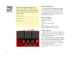
Input Connections.
The red RCA-type input is for the right chan-
nel; black is for the left channel. As with speaker
cables, you have many esoteric options as well
as “conventional” connection cables. At the very
least, use high quality RCA cables with gold plat-
ing and durable cable-to-plug connections. Cheap
cables can fail and lead to frustrating trouble-
shooting — who would ever suspect their connec-
tion cables?
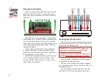
Double-check that “left goes to left”, “right goes
to right”, “plus (red) goes to plus (red)”, and “minus
(black) goes to minus (black)”.
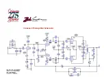
Line Voltage
This amplifier may be configured for operation
with 120 volts or 240 volts, 50 / 60 Hz. The change-
over must be performed by qualified personnel. It
is a standard under-the-chassis wiring configura-
tion. See the circuit diagram on page 12 for details.
When used with 240 volts, the AC line fuse must be
replaced with a 1.5 Ampere unit
.
Fuses
The rear panel line fuse is a 3 Ampere (1.5 Am-
pere for 240 volt operation), fast-blow type, and
should be replaced with
the same type and rating
if it ever needs replacing.
Do not, under any cir-
cumstances, use a “slow-
blow” fuse here.
The (rear panel) vac-
uum tube cathode fuse
(B+) is a 1.0 ampere and should be replaced with
the same type and rating. If the fuse blows during
bench testing, it may be temporarily replaced with
a 1.25 or 1.5 ampere fuse.
Do not, under any cir-
cumstances, use a “slow-blow” fuse here!
Normally, a 1.0 ampere fuse will be perfect for
music because the peak-to-average power ratio
of speech and music is about 10:1. If you find
that the 1.0 amp fuse blows with music, you may
replace it with a 1.25 ampere fuse, or even a 1.5
ampere unit.
Power Switch
Up is ON, down is OFF. There is no power-on
indicator except for the glow of the tubes, so you
will have to remember whether you turned it on
for about 10 seconds until you can see the tubes
glow. It is safe to switch the amplifier on and off
at will.
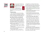
Adjusting the Output Tube Bias.
The front panel incorporates a multi-purpose
meter, one of the purposes of which is as a Tube
Bias Meter.
IMPORTANT: Turn your preamp volume control all
the way down while performing bias adjustments.
Use a small screwdriver and adjust the BIAS
control (located on the rear of the amplifier) for
100 mA
, after the unit has warmed up for about
20 minutes. The normal range to use is from 60 mA
to 120 mA, and changes here will vary the damp-
ing factor of the amplifier slightly. More current
increases the damping factor, whereas less cur-
rent provides a softer more tube-like sound.
The
design center is 100 mA
, and that should be
Summary of Contents for 27813
Page 1: ...Operating Manual c02 15 19...


