Berkeley
Nucleonics
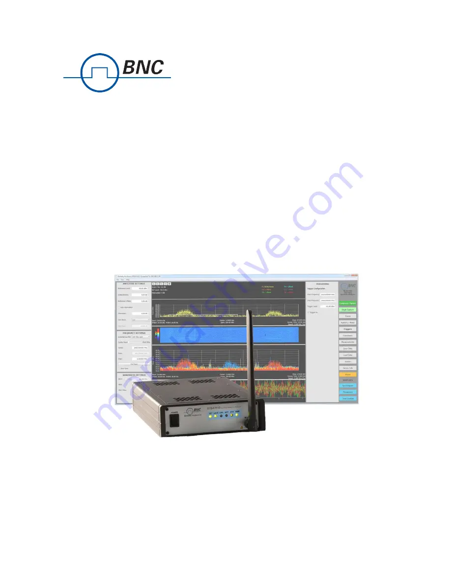
RTSA7550
Real-Time
Spectrum
Analyzer
User
Guide
Version 4.0
Berkeley Nucleonics Corporation - 2955 Kerner Blvd. - San Rafael, CA 94901
800-235-7858 or LiveChat @ www.berkeleynucleonics.com
Page 1: ...Berkeley Nucleonics RTSA7550 Real Time Spectrum Analyzer User Guide Version 4 0 Berkeley Nucleonics Corporation 2955 Kerner Blvd San Rafael CA 94901 800 235 7858 or LiveChat www berkeleynucleonics com...
Page 2: ...is greater than 30 days then BNC will honor this remaining warranty period BNC EXPRESSLY DISCLAIMS ALL OTHER WARRANTIES AND CONDITIONS WHETHER EXPRESS OR IMPLIED INCLUDING WITHOUT LIMITATION WARRANTIE...
Page 3: ...onnecting the RTSA7550 Analyzer Directly to a Computer 14 Connecting to the RTSA7550 Analyzer Across a Network 16 Administration Console 18 Connecting via Your Web Browser 18 Configuring the RTSA7550...
Page 4: ...tus and ACT Indicator LEDs 31 Hardware Reference 32 System Specifications 32 SMA Connectors 32 Ethernet RJ 45 Port Pinout 33 GPIO Port Pinout 33 USB Console Port Pinout 34 RJ 45 Straight Through Ether...
Page 5: ...arning This symbol means danger You are in a situation that could cause bodily injury Before you work on any equipment be aware of the hazards involved with electrical circuitry and be familiar with t...
Page 6: ...ormation available RTSA7550 serial number which is located on the identification label on the RTSA7550 s underside The product version The firmware version running on the RTSA7550 Versions of BNC soft...
Page 7: ...me Spectrum Analyzer provides Gigabit Ethernet for stand alone remote and distributed applications BNC supports a rich set of industry leading standard protocols and APIs enabling the RTSA7550 to easi...
Page 8: ...and analog IQ ports The Rear Panel The rear panel of the RTSA7550 the right side of the picture above contains the power input 10 MHz reference clock I O hardware reset push button HIF output analog I...
Page 9: ...erview of the BNC RTSA7550 BNC RTSA7550 Real Time Spectrum Analyzer User Guide 9 Berkeley Nucleonics Corporation 2955 Kerner Blvd San Rafael CA 94901 800 235 7858 or LiveChat www berkeleynucleonics co...
Page 10: ...ation of synthetic fibers and dry atmosphere Always follow these steps to prevent ESD Warning Never open the front or rear panels of the RTSA7550 as personal injury may result and opening the chassis...
Page 11: ...na can cause permanent damage to the receiver 1 Screw the antenna on to the RTSA7550 RF IN antenna input SMA jack Carefully turn the antenna screw by hand until it encounters resistance See System Spe...
Page 12: ...eiver do not install or operate the RTSA7550 within 2 feet 60 cm of devices such as Wi Fi access points that transmit more than 15 dBm power 12 BNC RTSA7550 Real Time Spectrum Analyzer User Guide Berk...
Page 13: ...7550 supports any IP network topology connected via its Ethernet port including a direct connection to a computer across an RJ 45 Ethernet cable as per the Connecting the RTSA7550 Analyzer Directly to...
Page 14: ...nd is described in the section Using the administration console requires a connection to the RTSA7550 via its Ethernet port Connection to the RTSA7550 using dynamic or static IP allocation is describe...
Page 15: ...ss Verify the host PC s IP configuration using the PyRF Discovery Tool With a Windows OS open a Command window and type ipconfig to show the IP addresses assigned to each interface The Ethernet interf...
Page 16: ...vides instruction on connecting the RTSA7550 to a computer across a routed local network whether on the same subnet or across different subnets or across a routed wide area network such as the Interne...
Page 17: ...onsult with your network administrator 6 Use the PyRF Discovery tool or the S240 Real Time Spectrum Analysis Software both provided by BNC to determine the RTSA7550 s assigned IP address In order for...
Page 18: ...or remotely Connecting via Your Web Browser Connect to the RTSA7550 Administration Console by entering the IP address of your RTSA7550 into a web browser s web address dialog The IP address is shown...
Page 19: ...time manually is selected then enter the date and time based on your local time zone 4 If Use current PC time is selected then the data and time fields will be populated automatically 5 If NTP is sel...
Page 20: ...Once the Apply is clicked the new configuration will take effect immediately and the current configuration and web page will no longer be valid Updating the RTSA7550 s Firmware This section will step...
Page 21: ...n of the BNC_RTSA7550_firmware_vX Y Z img or similar img firmware image file and then click the Install button When the firmware image for the intended product version is installed the following Firmw...
Page 22: ...IP connection method is used Customizing the RTSA7550 Calibration The RTSA7550 supports user defined calibration settings if you do not want to use the BNC default calibration settings This allows yo...
Page 23: ...age The RTSA7550 Device Calibration page will appear 2 Click Browse An Explorer window will open on your PC 3 Navigate to the location of the desired file and click Open The selected file name appears...
Page 24: ...date 3 Created date and time of the calibration file as listed in the created field For example if two calibration files have the same firmware version then the file source is compared If the source i...
Page 25: ...s internet connected administration console Performing this type of restart is equivalent to a power on reset 1 Referring to the previous Status web page click on the Device Restart link in the left c...
Page 26: ...is powered on press and hold the reset button locate in the rear panel of the box for at least 5 seconds by inserting a paper clip or similar object 3 The STS LED will blink green fast several times t...
Page 27: ...erly installed by inspecting Control Panel Device Manager Ports COM LPT at which a Silicon Labs CP210x USB to UART Bridge COM7 or equivalent COM should appear without error If the driver has not appea...
Page 28: ...50 Programmer s Guide that is associated with the firmware release of your RTSA7550 for the SCPI commands to use with your RTSA7550 via the USB console terminal window The firmware release version of...
Page 29: ...iguration 1 Follow the instructions above to install the USB drivers on your PC and connect to the USB console 2 Refer to the illustration below as an example enter the following SCPI commands substit...
Page 30: ...Status Off Not receiving power from power adapter Green All internal power conditions are good Orange or Red One or more of the internal power conditions are not present or corrupted Status STS Indic...
Page 31: ...rence selected but PLL cannot lock to it RF Chain PLLs LOCK Indicator LED Referring to the above illustration the LOCK LED indicates whether the clock sources in the selected RF chain are of sufficien...
Page 32: ...r product specification SMA Connectors The SMA connectors on the front and back panels are all female jacks with 50 nominal impedance The following table outline the maximum and minimum power level re...
Page 33: ...Ethernet RJ 45 Port Pinout Pin Signal 1 BI_DA 2 BI_DA 3 BI_DB 4 BI_DC 5 BI_DC 6 BI_DB 7 BI_DD 8 BI_DD GPIO Port Pinout The GPIO General Purpose Input Output port supports extended hardware capability...
Page 34: ...the EXT IN OUT IO pins is application specific and thus could vary Refer to ThinkRF s Application Notes or contact BNC support for more information USB Console Port Pinout Pin Signal 1 5 VDC 2 Data 3...
Page 35: ...able BNC RTSA7550 Real Time Spectrum Analyzer User Guide 35 1 2 3 4 5 6 7 8 1 2 3 4 5 6 7 8 1 2 3 4 5 6 7 8 1 2 3 4 5 6 7 8 Berkeley Nucleonics Corporation 2955 Kerner Blvd San Rafael CA 94901 800 235...