BMS SR220 Operation Manual Download Page 1


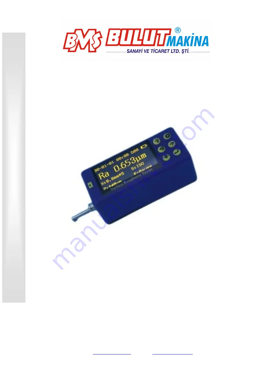
Surface Roughness Tester   

SR220


BMS Bulut Makina Sanayi ve Ticaret Ltd. Şti. 

Kocaeli KOBİ OSB Köseler Mahallesi, 

6. Cadde No: 20/2 Dilovası / KOCAELİ / 

TURKEY


Phone: +90 262 502 97 73-76 / +90 262 503 06 51 

Web: 

www.bulutmak.com

      e-mail

[email protected]


OPERA

TI

ON MAN

UAL


Summary of Contents for SR220

Page 1: ...R220 BMS Bulut Makina Sanayi ve Ticaret Ltd Şti Kocaeli KOBİ OSB Köseler Mahallesi 6 Cadde No 20 2 Dilovası KOCAELİ TURKEY Phone 90 262 502 97 73 76 90 262 503 06 51 Web www bulutmak com e mail bms bulutmak com OPERATION MANUAL ...

Page 2: ...T OPERATION 9 3 1 PREPARATION BEFORE MEASUREMENT 9 3 2 SWITCH ON 9 3 3 STYLUS POSITION 10 3 4 CALIBRATION 10 3 5 GETTING STARTED 11 3 5 1 Start measuring 11 3 6 RESULT DISPLAY 11 3 6 1 Parameters 11 3 6 2 Profile Graphic 11 3 6 3 Store read measurements 12 3 6 4 Print measurements 12 3 6 5 Connected with PC 14 3 6 6 Remote measurement 14 3 6 7 SD card 14 4 MAIN MENU 14 4 1 MEASUREMENT CONDITION SE...

Page 3: ...OUGHNESS PARAMETERS RANGE 22 9 REFERENCES 22 9 1 TERMS 22 9 1 1 Terms 23 9 1 2 Traversing length 23 9 2 DEFINITION OF PARAMETERS 24 9 2 1 Arithmetic Mean Deviation of Profile Ra 24 9 2 2 Root mean square Deviation of Profile Rq 24 9 2 3 Maximum height of the profile Rz 24 9 2 4 Total Peak to valley Height Rt 24 9 2 5 Maximum profile peak Rp 24 9 2 6 Maximum valley depth Rv 25 9 2 7 Average distanc...

Page 4: ... surface This signal is fed to the data acquisition system after amplification and level conversion The collected data is filtered and the parameters are computed via the ARM chip The measurements are displayed on the OLED A Bluetooth printer can be connected wirelessly All measurement parameters can be printed This tester can also communicate with the PC through the data cable so as to perform ad...

Page 5: ...ver Charger Data cable Parameters according to ISO 4287 Symbol Arithmetic Mean Deviation Ra Root Mean Square Deviation Rq Maximum Height Rz Total Height Rt Max Profile Peak Height Rp Max Profile Valley Depth Rv Mean Width RSm Material Ratio Rmr Kurtosis Rku Core Roughness Depth Rk Reduced Peak Height Rpk Reduced Valley Height Rvk Material Portion Mr1 Material Portion Mr2 ...

Page 6: ...5 1 4Layout of the instrument 1 4 1 Main unit 1 4 2 Pickup ...

Page 7: ...utton in the main screen to start the wireless Bluetooth printer to print all measurements 2 After entering the other screens the button will be set as the Right arrow Set Menu 1 Press this button in the main screen to enter fast Setting of measurement conditions to set and change various measurement conditions following the cursor 2 Press and hold this button to enter the main menu 3 After enteri...

Page 8: ...trument charging will start During charging the LED red is ON the LED green is ON after the battery is fully charged Disconnect the power It takes about 3 to 4 hours to charge The input voltage of charger is 100 240V 50 60Hz AC maximum current 0 2A output 5V DC maximum charging current of about 500 mA This instrument uses a lithium polymer battery no memory effect You can charge at any time and th...

Page 9: ... and press Return to enter System Set menu then select Clock Set and press Return to enter Clock Setting screen In general press Up Down arrow to switch and choose the item press Left Right arrow to adjust the number 2 2Units of measurement In main screen press and hold Set to enter the main menu then select Measure Set and press Return Press Up Down to select the Unit Press Return to directly cha...

Page 10: ... pickup perpendicular to machining texture of the measured surface of the workpiece d Keep the instrument and the pickup parallel with the measured surface during measuring e During measuring keep it away from vibration magnetic fields wind and other external environments which will affect the measurements Measurement direction Instruction Correct and normative operation is the precondition to obt...

Page 11: ...rument is accompanied with a calibration specimen Before the measuring test the calibration specimen using the instrument Normally as the difference between the measurement and the value of the specimen is within the range of the instrument the measurement is valid It is unnecessary to adjust The tester can be used for direct measuring If the difference between the measurement and the value of the...

Page 12: ... can start measuring In the main screen press the Start button to begin measuring After sampling is completed filtering of the sampled data starts After filtering is completed all the parameters are calculated Tips If you accidentally touch the power button in the measurement state the instrument will be shut down After booting the pickup will be reset Do not intervene the pickup now After resetti...

Page 13: ...o enter the Store screen Press Return to confirm and store current data You can modify the group No If the space is full select delete in the Memory Data menu Be careful for deleting data to avoid any mistakes 20 groups of measurements can be stored 2 Load history data To load the history data enter Memory Data menu and then select Load Mea Data Find the desired group No Press Return to load the d...

Page 14: ...ect Printer Pair from Print Results menu item Press Return to pair the printer and the roughness tester After about 3 seconds display Pairing successful Press Set to return to the main screen and you can print Print Setting screen 1 Start printing In the main screen press Right arrow to print the measurement parameters and profile graphics to the printer 2 Paper All printed contents SR200 Surface ...

Page 15: ...r about 3 seconds display Pairing successful Press Set to return to the main screen and you can use the remote controller 3 6 7 SD card The instrument is equipped with an SD card for remote software upgrade Upgrade procedure 1 Receive the new version of software from the manufacturer by e mail 2 Copy the software to the SD card insert the SD card into the USB port of PC via an adaptor 3 Remove the...

Page 16: ...ress and hold Set to enter Menu Setting mode Select Measure Set to modify Sampling Length Evaluation Length Range Filter Standard Parameters C Rmr C RPc Rmr Rδc Unit of Measurement 4 2System Setting In the main screen press and hold Set to enter Menu Setting mode Select System Set to enter System Set menu item Under this menu you can set the following contents Key Buz Warning Buz Power saving time...

Page 17: ...calibration 6 Common Faults 7 Accessories 7 1Height support and pickup holder When the measured surface of the workpiece is smaller than the bottom surface of the instrument you can use the pickup holder and height support in the following optional accessories to support to complete the measurement as shown below Height support and pickup holder Tips 1 The dimension L in Figure 1 cannot be less th...

Page 18: ...e to the workpiece surface check the stylus position on the screen carefully It is OK as the pointer stays in the middle of the display When the Ra value of the measured surface is small it is recommended to use the measurement platform Start the measurement with a remote controller in order to reduce the impact of the external environment on the measurements To use special pickups such as apertur...

Page 19: ...c Adjust the body of pickup level and check visually Check whether the stylus position is near the center d Lift the pickup in proper direction Wrong direction will cause damage to the pickup 7 3 3 Calibration 1 Measure the multi line specimen 2 Read the Ra value 3 Compare it with the calibration specimen 7 3 4 Precautions 1 Be careful to plug the pickup Do not touch the guide and the stylus which...

Page 20: ...1 Calibrate the curve surface pickup using a single line specimen 2 Calibrate Calibration As shown in the figure incline the single line model at certain angle so that the guide and the stylus pass the line in order rather than at the same time which is not the true depth After measuring observe the profile graphics There is a rectangular deep groove and the groove depth is the single line value T...

Page 21: ...Be careful especially as the pickup contacts with the workpiece 3 Adjust the body of pickup level and check visually Check whether the stylus position is near the center 4 Lift the pickup in proper direction Wrong direction will cause damage to the pickup 7 5 3 Calibration 1 Measure the multi line calibration specimen 2 Read the Ra value 3 Compare it with the specimen 7 5 4 Precautions 1 Be carefu...

Page 22: ...first and then low 2 Measure 3 Adjust the stylus near the center 7 6 3 Calibration 1 Calibrate the small bore pickup using the multi line calibration specimen 2 Calibrate a Measure the multi line calibration specimen b Read the Ra value c Compare it with calibration specimen 7 6 4 Precautions 1 Be careful to plug the pickup Do not touch the guide and the stylus which are key parts of the instrumen...

Page 23: ...direction radius 40mm Sliding speed lr 0 25 Vt 0 15mm s lr 0 8 Vt 0 5mm s lr 2 5 Vt 1mm s Return Vt 1mm s Value error Not more than 10 Value fluctuation Not more than 6 Power Built in lithium polymer rechargeable battery 8 4V 800mA charger Dimension 112 50 47mm Weight Approx 360g 8 1Standard code and name Code Name ISO 4287 International standard DIN 4768 German standard JIS B601 Japan industrial ...

Page 24: ...litude transmission characteristic is the same as the RC filter basically no phase difference The amplitude parameters obtained from the RC filter and PC RC filter are the same GAUSS Gaussian filter The latest roughness filter in line with GB T 18777 2002 Geometrical product specifications GPS Surface texture Profile method Metrological characteristics of phase correct filters 9 1 2 Traversing len...

Page 25: ...e value of the vertical coordinate value within one sampling length l dx x Z l Rq 0 2 1 9 2 3 Maximum height of the profile Rz The sum height between maximum profile peak height Rp and maximum profile valley depth Rv within one sampling length 9 2 4 Total Peak to valley Height Rt The sum height between maximum profile peak height and maximum profile valley depth within the assessment length 9 2 5 ...

Page 26: ...ithin an evaluation length 9 2 7 Average distance of profile single peak RS Average distance of profile single peak Xs within a sampling length 9 2 8 Average width of profile unit RSm Average width of profile unit Xs within a sampling length m i XSi n RSm 1 1 ...

Page 27: ...mum profile height RyJIS Same as 9 2 3 Rz 9 2 11 Profile inclination Rsk The ratio of the average of cubic of ordinate values Z x and the cubic of Rq within a sampling length lr dx x Z lr Rq Rsk 0 3 3 1 1 9 2 12 Average peak to valley height R3z The average of the vertical distances between the third peak and the third valley of various sampling lengths within the evaluation length n i i zi R z R ...

Page 28: ...t first Then calculate RPc peak counts A peak higher than C value and an adjacent valley lower than C value form a number of RPc peak count RPc is calculated and assessed based on the evaluation length using the following formula cm Peaknumber cm RPc length Evaluation count Peak 9 2 15 Profile support rate curve Rmr Curve of profile support rate v s horizontal positions 9 2 16 Profile support leng...

Reviews: