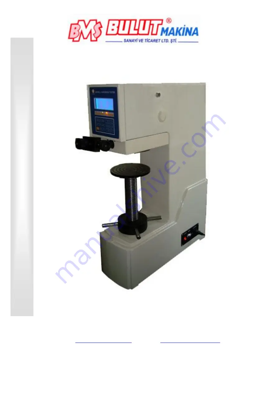
Bms Bulut Makina BMS 3000-OBLC Operational Manual Download Page 1

BMS 3000-OBLC 

Brinell Hardness Tester 


BMS Bulut Makina Sanayi Ve Ticaret Ltd. Şti. 

İkitelli Organize Sanayi Bölgesi Dolapdere Sanayi Sitesi 

Ada 4 No : 7-9 Başakşehir / 

İSTANBUL-TURKEY 

Phone : +90 212 671 02 24 / 671 02 25 Fax : +90 212 671 02 26 

web : 

www.bulutmak.com

   e-mail : 

[email protected]


OPERA

TI

ONAL

 MANUA

L


Summary of Contents for BMS 3000-OBLC

Page 1: ... Makina Sanayi Ve Ticaret Ltd Şti İkitelli Organize Sanayi Bölgesi Dolapdere Sanayi Sitesi Ada 4 No 7 9 Başakşehir İSTANBUL TURKEY Phone 90 212 671 02 24 671 02 25 Fax 90 212 671 02 26 web www bulutmak com e mail bms bulutmak com OPERATIONAL MANUAL ...

Page 2: ...ation 3 4 Key Function 4 4 1 Operation Panel Function 4 4 2 Display Interface 5 4 3 Use 7 5 Adjustment Attention 9 6 Electric Principle Introduction 10 7 Use of Microscope 10 7 1 Zeroing of Micrometer Eyepiece 11 7 2 Test Indention Diameter 11 7 3 How to Read Drum Wheel 13 8 Brinell Hardness Calculation 13 ...

Page 3: ...ificate 1 Manual 1 Dust cover 1 3 Installment and Adjustment 3 1 Unpacking and Installation 3 1 1 Unscrew the four nuts outside the box below lifting hardness tester remove the four mounting screws on the bottom put the hardness tester on suitable bench 3 1 2 Remove the pads between lifting shaft and indenter shaft using gasoline to lift anti rust oil wipe the top screw until the dry coated amount...

Page 4: ...on introduction 4 1 1 Based on testing requirements there are 612 5 29400N total of 10 test force according to the selected test force the corresponding indicator lights 4 1 2 Test condition display 3 phases loading unloading and dwell which the light will show 4 1 3 Key functions SETUP Continuous press SETUP twice setting interface will appear on the LCD on see Figure 7 You can press the and sele...

Page 5: ...o confirm then the corresponding hardness results will be displayed on the screen If you enter a number in error you can press before the press C OK key to delete the number entered PRINT If you choose printing out please click PRINT printer is optional accessory 4 2 Display Interface 4 2 1 Open power you listen di di initial interface displayed this time LED lit electric motor test then again di ...

Page 6: ...mode Set interface see Figure 7 by pressing to move the cursor to ALOAD press select the measurement mode boot settings for the automatic measurement AUTO After the settings finished press the key OK once to determine the selected operation and then OK key save the settings parameters system get into the working interface LOADING flashing see Figure 8 Figure 8 interface Note The initial dwell time...

Page 7: ...structure 4 3 2 Turn on the power switch the machine itself to initialize display the initial interface a large lever to enter the work automatically adjust the starting position Startup force value set in 612 9N 62 5Kgf position the boot time set to 15 seconds if you want to choose other security forces and load time testing please refer to the Features control panel 4 3 3 After preparation Put t...

Page 8: ...cal plane position and finally through the eyepiece micrometer 6 measured on the measurement methods are detailed in Chapter 8 Test force 62 5Kgf 250Kgf is 1 file Auto loading value 40Kgf 500Kgf 3000Kgf is a file Auto loading value 90Kgf Note Automatic loading hardness value shall be the minimum force value work Do not operate the roller will force exceeds this value too much as slightly larger th...

Page 9: ... 1 6 if the ball diameter Φ2 5mm sample roughness should be 0 8 or above in order to clear the edge of indentation to ensure the accuracy of measurements Sample surface should be no oxide plating and surface heat or other contaminants 4 3 9 Hardness test how power level power at all levels of testing should be used Table 3 in nominal value specified Figure 3 Hardness Ball diameter mm 0 102F D2 F D...

Page 10: ...al 1 5 In order to continuously improve the quality of the instrument the Company will appropriately update the instrument structure so that the contents of manual with slightly different equipment but does not affect the operation function without notice please forgive 6 Electric Principle Introduction HBC 3000 Electronic Brinell hardness change the past weight type loading method using CPU contr...

Page 11: ...o light gap at the critical state the light transmittance is very weak second line tangent shown in Figure 12 0 screw hole Figure 12 two thin close infinite Figure 13 drum reads 0 7 1 3 Check weather the reading on the measurement drum is the 0 shown in Figure 13 7 1 4 If 0 as has been offset to take in depth screw holes Allen wrench loosen screws rotate or move the measuring drum to drum reads 0 ...

Page 12: ...entation tip 7 2 6 D1 column by the number keys enter the measurement in the wheel drum and press OK confirm the readings How to read drum reading on later in this chapter for instructions If you enter a number in error you can delete by OK ago by C enter numbers By OK confirmed the cursor will automatically jump to D2 D2 asked to enter the number unit suddenly meters cm is the smallest measuring ...

Page 13: ...7 3 How to Read Drum Wheel Shown on Figure 19 You can see the scale of the main ruler is over 2 Therefore the readings on the main scale should be 200cmm suddenly meters Vice foot line on the scale just 40 feet on the main line of coincidence therefore deputy ruler of the reading of 40cmm suddenly meters The overall reading of 200 40 240cmm suddenly meters that is rotated by 240 cells Drum main sc...

Page 14: ...the D1 from the panel number keys enter 1 029 click OK key to confirm this time D2 marked jump from the panel number keys enter 1 031 then OK to confirm and then displayed on the screen 71 7HBW that the Brinell hardness value of this indentation Figure 21 Figure 21 71 7 HBW D1 1 029mm FORCE 62 5Kgf D2 1 031mm DWELL 15S DATA TIME NO 1 ...

Reviews: