


1
2
3
4
8
5
6
9
10
7
7
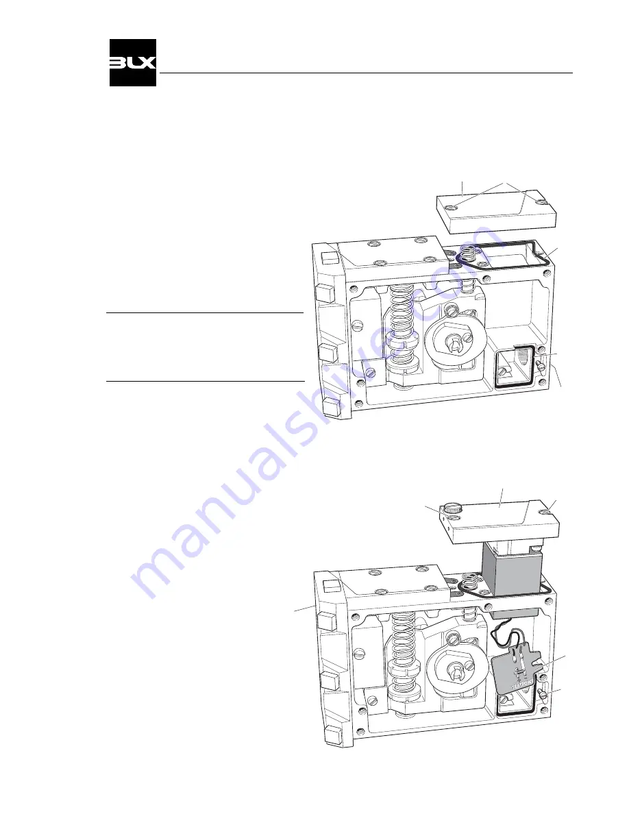
4. CONVERTING
4.1 Converting from V100P to V100E
1. Remove the front cover and indicator.
(see page 12)
2. Loosen the screws(1) and remove the
cover(2).
3. Unscrew the protective plug from the
I
E
-connection(8).
Please Note!
Check the seals(3 & 4).
Replace if they are damaged.
4. Insert the connection card(5) and the I/P-
converter(6) through the square hole in
the housing.
5. Secure the I/P-converter with the screws(7).
6. Install the connection card in its seat and
secure with the locking screw(10).
7. Plug the port(9) marked I
P
.
Threading requirements G 1/4" or 1/4" NPT
is indicated by the markings on the housing.
8. Connect the control signal (see page 10).
25
V100 Positioner
Summary of Contents for v100 positioner
Page 1: ......
Page 2: ......
Page 28: ...5 SPARE PARTS 5 1 Exploded drawing 26 V100 Positioner ...
Page 31: ...6 2 Dimensions 29 V100 Positioner ...
Page 32: ......