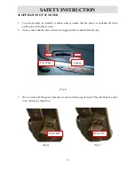
Bluesky S9 Venus User Manual Download Page 5

4.

Emergency Brake (Optional)

General

1.

Always use a seat belt, and keep your feet on the scooter all the time.

2.

Do not over load the scooter with it’s maximum weight capacity of 135kg (300 lbs)

3.

Do not attempt to lift or move a power scooter by any of its removable parts. Personal injury

and damage to the power chair may result.

4.

Never try to use your scooter beyond its limitations as described in this manual.

5.

Do not operate your vehicle if it is not functioning properly.

6.

Do  not  connect  any  electrical  or  mechanical  device  to  the  scooter.  Failure  to  obey  this

instruction may result in injury and will void the warranty.

7.

Never  use  electronic  radio  transmitters  such  as  CB,  walkie-talkies,  portable  computers  or

cellular phones while using the vehicle without first turning the scooter off.

Usage When Under The Influence Of Medication Or Alcohol

1. Check  with  your  physician  if  you  are  taking  any  medication  that  may  affect  your  ability  to

operate your power scooter safely.

2. Do  not  operate  your  scooter  while  you  are  under  the  influence  of  alcohol,  as  this  may  impair

your ability to operate your power scooter in a safe manner.

Electromagnetic interference (EMI) from Radio Wave Sources

The rapid development  of electronics, especially in the area of communications, has saturated our 

environment  with  electromagnetic  (EM)  radio  waves  that  are  emitted  by  television,  radio  and 

communication signals. These EM wave are invisible and their strength increases as one  approach 

the source. All electrical conductors act as antennas to the EM signals and, to varying degrees, all 

power  wheelchairs  and  scooters  are  susceptible  to  electromagnetic  interference  (EMI).  The 

Summary of Contents for S9 Venus

Page 1: ...1 USERS MANUAL S9 Venus Bluesky Mobility Pty Ltd 46 Surrey Road Keswick South Australia Visit www blueskymobility com au for contact details...

Page 2: ...2 Buttons Indicators 14 9 Usage Conditions 14 10 Characteristics 15 11 Operation of Control Panel 15 11 1 Temperature Meter 15 11 2 Clock 16 11 3 Odometer 17 11 4 Speedometer 19 11 5 High Low Speed T...

Page 3: ...3 TECHNICAL SPECIFICATIONS...

Page 4: ...r is switched off when getting on or off of the scooter 2 Always check that the drive wheels are engaged drive mode before driving Fig 1 3 Do not switch off the power when the scooter is still moving...

Page 5: ...nes while using the vehicle without first turning the scooter off Usage When Under The Influence Of Medication Or Alcohol 1 Check with your physician if you are taking any medication that may affect y...

Page 6: ...powered scooter movement that could result in serious injury 1 Do not turn on hand held personal communication devices such as citizens band CB radios and cellular phones while the powered scooter is...

Page 7: ...cause electronic malfunction or promote premature corrosion of electrical components and frame B Temperature Some of the parts of the power scooter are susceptible to change in temperature The control...

Page 8: ...8...

Page 9: ...o assemble your S9 scooter Please follow the procedure below 1 Tiller Positioning Press down the lever fold the tiller up to vertical position and let it lock into your preferred position See Fig 4 5...

Page 10: ...Connect both battery cables probably pole Red is positive black is negative Fig 7 Fig 8 ADJUSTMENTS FOR SEATING COMFORT A Armrest Position Adjustment Fig 9 Connected Turn the round plate and adjust t...

Page 11: ...seat by clockwise or counter clockwise direction Fig 10 Fig 11 B 2 Seat Position Adjustment Push the seat adjust lever upwards slide your seat backward or forward to your desired position let the lev...

Page 12: ...on Adjustment Buttons LED Indications LCD Screen LED Indications Right Indicator Headlight Parking Indicator Left Indicator Right Indicator control Parking lamp control MODE button Headlight control H...

Page 13: ...ining capacity and charging indicator 6 squares Battery icon 7 Headlight Blue LED Including Power Saving mode 8 Position Light Orange LED Placed inside headlight used while rainy or gloomy weather 9 B...

Page 14: ...arking Indicator Red LCD Backlight Illumination 700 mcd min Orange color Connecter CON1 20PIN 3 Usage Conditions ITEM SPECIFICATION Voltage DC 24 V Operation Voltage DC 16 32 V Storage Temperature 40...

Page 15: ...rrent VB 24 0V Dynamic 200 mA max backlight and all of LED illuminated Static 5 mA max Key Off status MA mA 5 Operation of Control Panel 5 1 Temperature Meter ITEM DESCRIPTIONS Operation Feature Tempe...

Page 16: ...r Setting Mode when 1 idle for more than 20 seconds 2 press for more than 2 seconds the system will save the last setting value automatically and back to Working Mode 5 2 Clock ITEM DESCRIPTIONS Toler...

Page 17: ...rease continually till the button released The setting value runs cyclically only 2 sec from 0 to 9 Exit Setting Mode Under Setting Mode when 1 idle for longer than 20 seconds 2 press for longer than...

Page 18: ...0000 99999 When the total distance ran to 99999km or 62149mile 99999 1 609mile the digits will be reset to zero 00000 TRIP Mode Press switching to TRIP mode Display Range 0 0 999 9 When the distance g...

Page 19: ...into a speed value When drive shaft runs at 2100 rpm speedometer will display 60km h Tolerance 15 20 Digits range 0 0 30 0 Display Rate 0 5 Setting Mode Units Switch Press for longer than 2 seconds to...

Page 20: ...previous waiting screen automatically once WIP accelerator stopped When SPEED was set on h speedometer will be disabled fit to non speedometer model and replaced by WIP accelerator operation screen F...

Page 21: ...TIONS Operation Features Press to switch High Low speed Control signals TRN with memory storage Take exterior turn switch as determinant signal Control signals TRN Symbols of Status High Speed Low Spe...

Page 22: ...nd icon is flashing 20 Warning LED is flashing Flicker Frequency 2 seconds Operation Characters The scale status only decrease won t increase When the remaining capacity was less than 30 warning sound...

Page 23: ...ncrease Take the PIN3 CH3 of charger as the determinant signal when CH3 is grounded L LCD will enter Charging Mode not limited by KEY ON or KEY OFF Any pressing of button will illuminate LCD backlight...

Page 24: ...e the function will be disabled Determinant Condition Power Saving Full Power React immediately Full Power Power Saving 5 sec delay Remarks 1 Loop Load 24V 50W max 2 With short circuit and overload pr...

Page 25: ...de Judge to be Reverse state the brake light flashes Reversing light Mode When the headlight and position light was turned on off and the brake light will be turn on off simultaneously Usage Condition...

Page 26: ...ess button once the right left park indicators start to flash warning sound act then press button again to turn off above indicators Usage Condition While 1 KEY OFF 2 Charging Mode 3 Sleep Mode the fu...

Page 27: ...tor start flashing with controller signal at same time the Error message code will show on LCD screen Flicker Frequency 1 second Controller message Flicker Message code symbol Status 1 Battery needs c...

Page 28: ...ill take a self test first the backlight and all LCD segments will be tuned on for 3 seconds then switch automatically to the default working mode LCD Backlight When press buttons the LCD backlight wi...

Page 29: ...e sure that they are not frayed cut or have any exposed wires SEMI ANNUAL CHECKS 1 Check the motor brushes We recommended that your authorized dealer inspect the brushes every six months or sooner if...

Page 30: ...a problem it will indicate with error message by flashing light on the power ON OFF light You must count the number of the flash and see the list to check what kind of error has happened according to...

Page 31: ...ck for open or short circuits Throttle may not be correctly set up Contact your service agent 8 Motor Volts Error Drive inhibited The motor or its wiring is faulty Check for open or short circuits Con...

Page 32: ...32 7 System Configuration ITEM SPECIFICATION Controller RHINO Series Wig Wag CTE NCW K001 Bulbs 24V 50W max 7 Circuit Diagram...

Page 33: ...33...

Reviews: