U
SER
M
ANUAL
WRAP
P
RODUCT
S
ERIES
4 U
SING THE
S
YSTEM
This chapter describes the basic features of a BlueGiga WRAP board and their usage. This includes using the
WRAP board as a Bluetooth LAN Access Point, Bluetooth Serial Port Cable Replacer, using the Web and
FTP servers for uploading content for browsing and downloading, as well as getting familiar with the utility
applications and the pre-compiled examples on the WRAP CD.
Using the features described in this chapter does not require the WRAP Software Development Environment
to be installed.
4.1 B
LUETOOTH
The Bluetooth server is started automatically at power-up. By default, it acts as a LAN Access point
following the Lan Access Profile specification. Also the Serial Port Profile is activated. The Bluetooth server
can be accessed and controlled (by applications or even interactively with a telnet client) using the socket
interface, described in the WRAP SDK manual. Currently, the maximum amount of simultaneous Bluetooth
connections is four due the amount of runtime memory a single LAN Access connection requires.
4.1.1
B
LUETOOTH
S
ERVER
S
OCKET
I
NTERFACE
P
ASSWORD
P
ROTECTION
The access to the Bluetooth Server Socket Interface is password protected by default. The password is
"buffy" and it can be set with the "setup" application (see section 3.3.1). Password is case sensitive. The
password must be typed as the first command after the server has replied with "READY." See the WRAP
SDK Manual for further details.
4.1.2 L
AN
A
CCESS
P
ROFILE
This profile is automatically started. By default, no authentication is needed. The default settings can be
changed with the "setup" application (see section 3.3.2), or runtime with the socket interface (see the WRAP
SDK Manual).
The WRAP board can also act as a LAN Access Client, but in this case it must be controlled manually using
the socket interface, described in the WRAP SDK Manual.
4.1.3 S
ERIAL
P
ORT
P
ROFILE
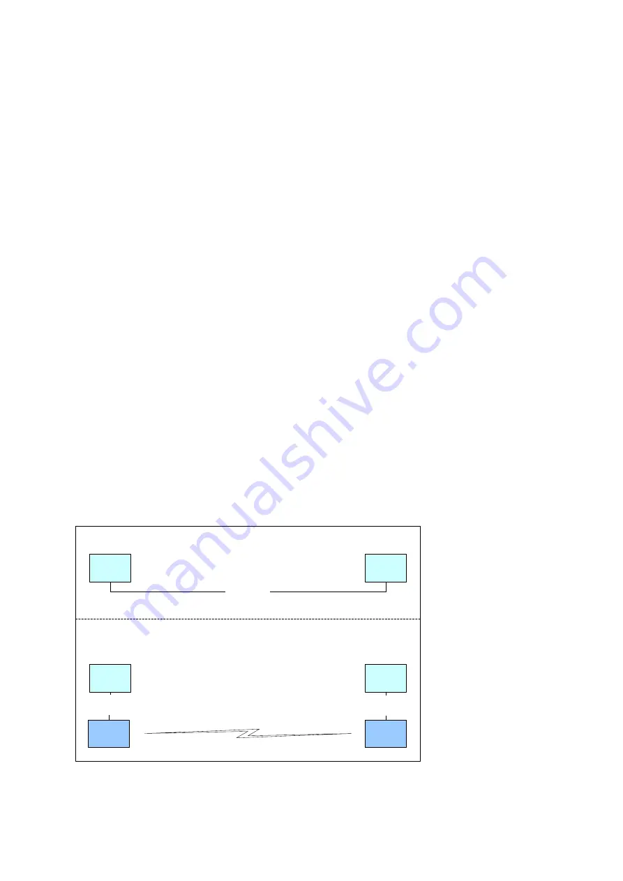
The Serial Port Profile is used to replace an RS-232 serial cable between two devices with a Bluetooth
connection. The physical setup is shown in Figure 3.
Serial Cable
User
device A
User
device B
Serial
Cable
User
device A
User
device B
Serial
Cable
WRAP
DevA
WRAP
DevB
Bluetooth
A)
B)
Figure 3. Serial Cable Replacement Physical Setup.
The state A) in the figure is the start situation with a serial cable connecting the devices. This cable is to be
replaced with a Bluetooth connection.
15 (26)


