


July 2014
Blue Sky Network
100258
ACH1000
Page 12
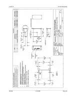
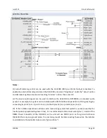
WIRE HARNESS FABRICATION & INSTALLATION CONSIDERATIONS
Referring to the appropriate section of this manual, assemble a wiring harness as required for the
installation. All wires must be MIL-SPEC in accordance with current regulations. Two-conductor
shielded wire must be used where indicated and be MIL-SPOEC-27500 or equivalent specification.
Shields should only be grounded at the Modem Unit end of the interconnect cable. Other ends remain
floating.
It is imperative that the correct wiring be used and that proper stripping, shielding, grounding, crimping
and soldering techniques be used at all times. Failure to correct techniques may result in poor
performance, electrical noise or unit failure.
POWER WIRING
To assure that the ACH1000 will operate properly down to its rated minimum input voltage, ensure that
power wires of at least the recommended size are connected in accordance with the installation
drawings. It is recommended that power and ground wires are a twisted pair to reduce signal noise.
GROUND BONDING
In order to assure installation characteristics match the DO-160 RF and Lightning test conditions, ensure
that ground wires of at least the recommended size are installed and these wires are connected to a
bonded aircraft ground.
Note:
The ACH1000 needs to be grounded for proper operation. See Pinout tables for correct pin
information.
CABLE & WIRE HARNESS ROUTING CONSIDERATIONS
The length and routing of cables must be carefully planned before starting the installation.
Avoid sharp bends in the cable.
Do not locate the cable near aircraft controls.
Observe all appropriate sections of FAR Parts 23, 25, 27, and 29, as well as AC 43.13-1 and AC
43.13-2 (latest revisions). Damage caused by improper installation will void product warranty.
In order to ensure optimum performance, the ACH1000 and associated wiring should be kept a
minimum of three feet from high noise sources and not routed with cables from high power
sources.