background image

6

ASI-4 

Instruction Manual

Section 3 - ASI-4 Unit
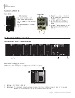
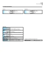
Front Panel

1.   

Status Indicator -


ON - Normal condition with 

Power and ASI input present.
Blinking - Indicates there is no ASI 

input.
OFF - Indicates there is no Power 

applied.

1.   

Power - 

3-pin female connector 

to  receive power cable from the 

MIPS-12 power supply.

2.   

ASI IN

 - BNC connector for ASI 

(Asynchronous Serial Interface) 

input.

3.   

ASI OUT

 - BNC connectors for ASI 

(Asynchronous Serial Interface) 

output.

Rear Panel

MIRC-12V Chassis with MIPS-12D Power Supply

MIPS-12D Power Supply Connections

All the connectors on the power supply are located on the rear panel.

1

2

1.  

AC Input

 - 100-240 VAC 50/60 Hz

2.   

DC Output

 -  The polarized D connector provides 12 sets of +12 VDC, +5 VDC and ground cables for the modules. 

Only 6 sets are used when the chassis is populated with 6 ASI-4 units.

Drawings are for illustration purposes only and are not to scale

3.1 Rack Chassis and Power Supply Units

6507 

(1 of 6)

7722D

7715

1.

1.

2.

3.

MIPS-12 

POWER SUPPLY 

STOCK NO. 7722C 


POWER 

STATUS

ASI-4

STATUS

ASI-4

STATUS

ASI-4

STATUS

ASI-4

STATUS

ASI-4

STATUS

ASI-4

Summary of Contents for ASI-4

Page 1: ... rights reserved Specifications are subject to change without notice Trademarks are the property of their respective owner ASI 4 ASI Splitter Model Stock No Description ASI 4 6507 1 4 ASI Splitter Accessories Model Stock No Description MIPS 12D 7722D Power Supply MIRC 12V 7715 Chassis 651226700A Status Date Document No Issue No Author Active December 5 2011 651226700A 1 KK ...

Page 2: ...gue Laboratories Inc One Jake Brown Road Old Bridge NJ 08857 Document Number 651226700A Printed in the United States of America All product names trade names or corporate names mentioned in this document are acknowledged to be the proprietary property of the registered owners This product incorporates copyright protection technology that is protected by U S patents and other intellectual property ...

Page 3: ...tions before you operate the unit Retain all safety and operating instructions for future reference Heed all warnings on the unit and in the safety and operating instructions WARNING TO PREVENT FIRE OR SHOCK HAZARD DO NOT EXPOSE THIS UNIT TO RAIN OR MOISTURE NOTE TO CATV SYSTEM INSTALLER This reminder is provided to call the CATV System Installer s attention to Article 820 40 of the NEC that provi...

Page 4: ...lt protection For added protection during a lightning storm or when the unit is left unattended and unused for long periods of time unplug it from the wall outlet and disconnect the lines between the unit and the antenna This will prevent damage caused by lightning or power line surges Do not locate the antenna near overhead power lines or other electric light or power circuits or where it can fal...

Page 5: ...complement digital headend products that can utilize an ASI input for EAS Emergency Alert System applications or any application requiring splitting of an ASI signal The ASI 4 can be deployed in a daisy chain configuration to provide additional outputs as required Modular design allows installation of up to six units in 2RU Compact design allows 6 modules in a 2 RU rack chassis DVB ASI Input compl...

Page 6: ...utput Rear Panel MIRC 12V Chassis with MIPS 12D Power Supply MIPS 12D Power Supply Connections All the connectors on the power supply are located on the rear panel 1 2 1 AC Input 100 240 VAC 50 60 Hz 2 DC Output The polarized D connector provides 12 sets of 12 VDC 5 VDC and ground cables for the modules Only 6 sets are used when the chassis is populated with 6 ASI 4 units Drawings are for illustra...

Page 7: ... LED Dimensions W x D x H ASI 4 Module MIPS 12D Power Supply MIRC 12V Rack Chassis 2 3 x 7 5 x 3 5 inches 58 x 191 x 89 mm 4 2 x 7 5 x 3 5 inches 106 x 191 x 89 mm 19 0 x 12 0 x 3 5 inches 483 x 305 x 89 mm Power ASI 4 Module MIPS 12D 5 VDC 540 mA 110 220 VAC 50 60 Hz input 5 12 VDC output Power Dissipation ASI 4 Module 2 75 W Weight ASI 4 Module Fully Loaded Chassis 1 0 lb 0 5 kg 16 4 lbs 7 5 kg ...

Page 8: ...ilable from BT on request VideoCipher DigiCipher are registered trademarks of Motorola Corp Rev 5 6 2009 Blonder Tongue Laboratories Inc Limited Warranty Blonder Tongue Laboratories Inc BT will at its sole option either repair or replace with a new or factory reconditioned product as BT may determine any product manufactured by BT which proves to be defective in materials or workmanship or fails t...

Reviews: