REAR PANEL CONNECTIONS
P20
1. POWER SWITCH: Switches mains power on/off to internal
components, however please note that mains power is still
applied to this unit even though this switch may be off.
2. FUSE HOLDER: fitted with 20mm T 2A fuse inside.
" IMPORTANT:"
Remove the mains plug from the mains socket before attempting
to check/ replace the fuse located on this fuse holder.
3. MAINS CABLE INLET JACK: Please ensure that the input cable strain relief
bush is intact and has not been damaged.
4. WARNING ICONS: Please be aware that this unit contains high voltages,
and should not be opened, please refer to page 2 of this manual.
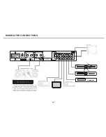
5/6. LOUDSPEAKER OUTPUTS. Please ensure that +/- connections are made
properly between rear of the amplifier and loudspeakers. Ensure wires are
not frayed or touching.
7. LINE OUTPUT SOCKETS: This is for connection to external amplification or
recording equipement.
8. TV INPUT SOCKET.
9. TAPE INPUT SOCKET.
10. AUX INPUT SOCKET.
11. DAB TUNER INPUT SOCKET.
12. CD INPUT SOCKET.
13. PHONO INPUT SOCKET. (For the connection of a turntable)
14. PHONO TERMINAL EARTH POST. It is necessary to provide a chassis
earth connection between the turntable and the amplifier. Failure to do
this will result in a buzzing or humming noise from the loudspeakers.
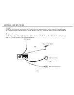
15. AM radio antenna.
16. FM radio antenna.
-
+
-
+
Model
:
VR 100
Hi-Fi Stereo Receiver
Power Rating
:
AC 230V 50Hz
Max Power Consumption
:
150W
15
16
Summary of Contents for VR 100
Page 2: ...VR 100 8 9 10 11 12 5 6 7 13 ...
Page 3: ......
Page 4: ......
Page 11: ......
Page 12: ...S 11 ...
Page 13: ...S 12 ...
Page 14: ...K 4 0 S 13 3 3 ...
Page 17: ...SAFETY INSTRUCTIONS Notes On Use P16 ...
Page 24: ...INSTALLATION AND POSITION V 1 0 0 V 100 P23 ...
Page 27: ......


