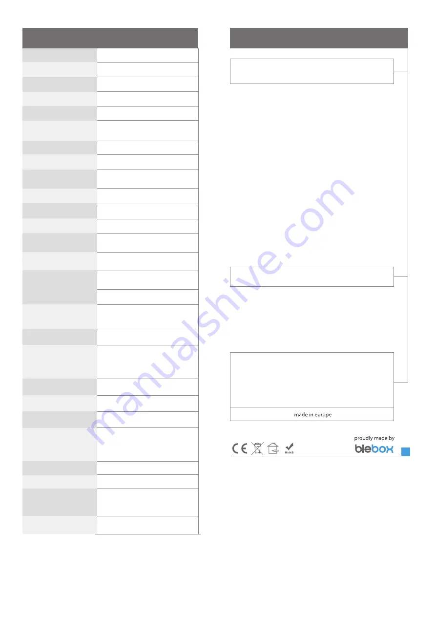
TECHNICAL SPECIFICATIONS
yes
2pcs (main probe and optional safety probe)
llogical, pushbutton, short circuited to N,
configurable
monostable (push-button), not-illuminated
blinking blue diagnostic diode (option to
switch off in the controller settings)
230 V AC
maximum load
16A / 230V AC, 16A / 24V DC
measurement range
from -55°C to 125°C
± 0,5°C in the range of -10°C to 85°C
measurement accuracy
number of pushbutton inputs
1
maximum power
inputs type
3680VA for 230V AC (for resistive load
e.g. heater)
temperature probe
inputs type
energy consumption
supply voltage
type of outputs
galvanic isolation
<1W
2.4 GHz
open
Apple iPhone, Apple iPad, iPad Mini,
Android, computers and mobile
devices supporting HTML5
number of outputs
1
IP20
μWiFi, compatible with WiFi, 802.11g
bi-directional, encrypted
made of polyurethane composition not
containing halogens, self-extinguishing
for thermal class B (130 °C)
supported switches
controller signaling
in a flush-mounted box (deepened
or double), in the receiver housing
- e.g. a heater, air conditioner
from -20°C to 50°C
controller operating
temperature
communication standard
transmission type
radio frequency
API
encryption
compatible devices
and systems
dimensions
housing
protection level
mounting method
41,5 x 47 x 12 mm
number of supported probes
mode
direct connection (as Access Point), Wi-Fi
connection via a stan- dard router,
connection with access from any location in
the world (requires only access to the
Internet)
WPA2-PSK and authenticated encryption
with associated data (AEAD)
for more information visit our website
www.blebox.eu
or send us an email to: [email protected]
support is available at [email protected]
ADDITIONAL INFORMATION
SOFTWARE UPDATE
LOCATION AND TIME OF THE DEVICE,
SCHEDULE
To update the software in the controller, connect it to your home WiFi network
(see "Access Point and WiFi settings" section) which is connected to the
Internet. Go to “Settings” (icon at the top-right corner of the screen) and click
the "Get new firmware" button in the final section on settings. Wait about 1
minute, do not close the interface and don’t perform other actions. The device
will download the latest software. The software version number, hardware
version and device identifier can be read at the bottom of the settings screen.
The controller has the ability to work according to a given schedule. To make
this possible, set the device's time. Go to settings in the "Device time" section,
click "Change timezone". Then select your region and location from the list,
confirm your selection clicking the "Save" button. The device will synchronize
its time with the server time (if the controller is in a WiFi network with access
to Internet) or it will download time from the phone / tablet. It is recommen-
ded that the controller is always connected to a WiFi network with Internet
access so that it can automatically synchronize its clock.
To be able to control devices using the local sunrise and sunset, you must also
select the location of the controller. You can specify the location of the device
using a smartphone or tablet. In the section "Device location", click "Set
locations". Browser will ask whether to share locations - allow. In the "Coordi-
nates" field, should appear the approximate coordinates of your location. If
the "Set locations" button blinks red with the word "Error", or the "Coordina-
tes" field did not change the value from "Not set" to numeric data, a failurehas
occurred during the location download. You should make sure that the phone
/ tablet has a GPS module and that the sharinglocation service is enabled on
the phone.
Adding schedule entries can be performed by clicking the "Add item" button
in the "Schedule" section of settings. You can select the days in which the task
will be performed, the type of entry (at a specific time, or relative to sunrise /
sunset - only having a correctly set location) and set the parameters of the
task. The set tasks will be visible as a list, individual entries can be edited or
deleted.
relay, galvanic isolation


