


BM100
MONOBLOCK DIRECTIONAL CONTROL VALVES
|
INSTRUCTIONS MANUAL
9
Before installing the product, check that it has not been
damaged during internal transport.
Step 1.
Install the valve in shock and vibration free areas. While moving the valve do not cause accidental bumps or shocks. The valve must be
secured with M10 screws. Apply thread-loch accessories. Mounting position is irrelevant as long as the valve is resting on a rigid and
perfectly flat surface; this is necessary so that the tightening of the screws does not cause harmful deformation.
Step 2.
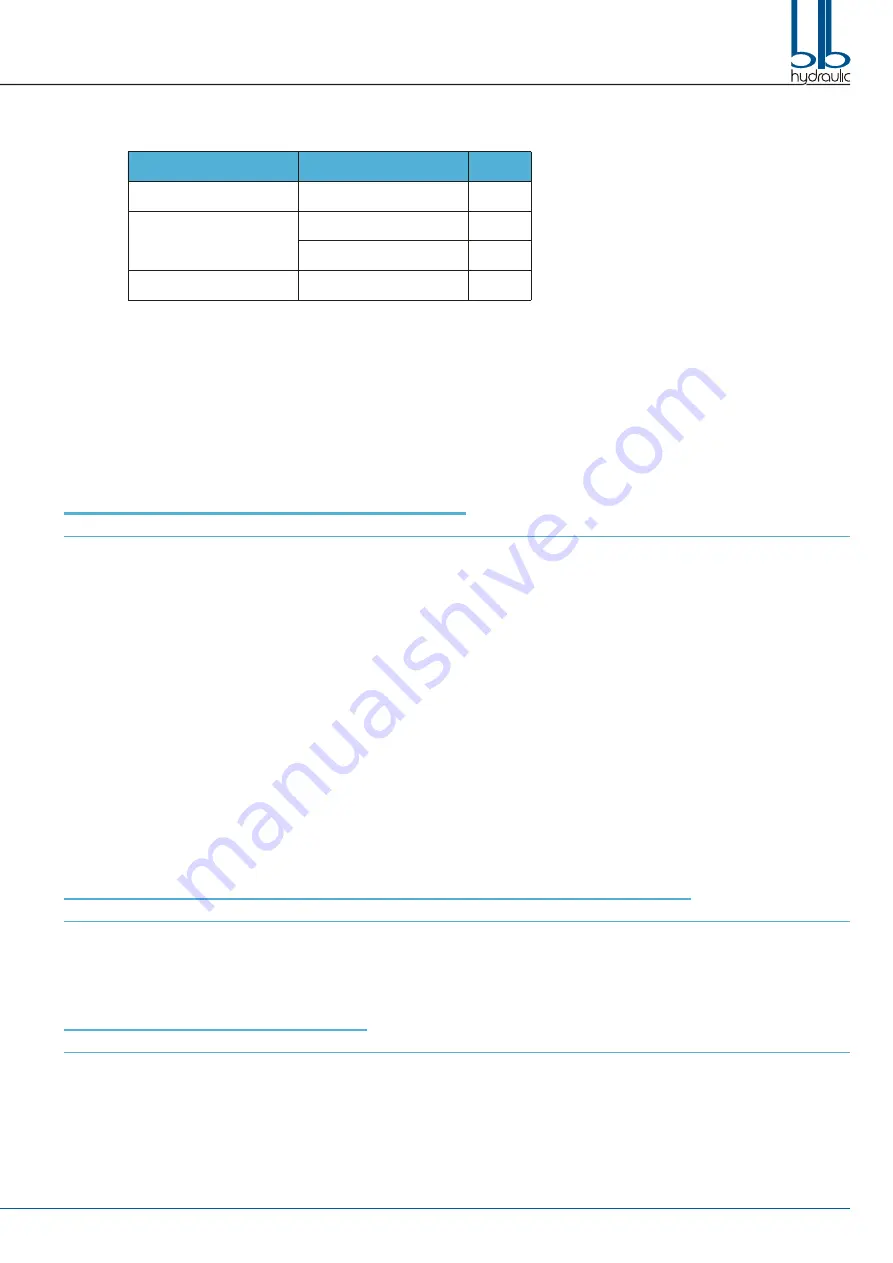
Use hoses and fittings suitable for indicated max flow and pressure. It is strictly prohibited the usage of conic fittings and the reversal of
connections between inlet (P, P2) and tank (T, T2) lines. Remove the protective plugs from the valve ports just before connecting the hoses
to prevent contamination of the circuit with dust or other materials. Do not use wrapped on threads to seal. Tighten fittings with the torque
indicated in the table.
Step 3.
Before starting, flux oil from an auxiliary system. Start the system and then operate the actuators individually and not under load. Operate
slowly until the system is filled with oil. Set the relief valve and carry out a complete test of the system. Do not perform calibration of valves
without having first applied a pressure gauge on the inlet section of the valve and on line where deemed necessary.
CHANGING THE VALVE SPOOL AND SEALS
(See drawing 1)
:
Step 1.
Remove the Handle (Part 3).
Step 2.
Remove the Screws (Part 6.2) with a 5 mm hex key and remove the Spool Control Cap (Part 6).
Step 3.
Using a 5 mm hex key remove the Spool Control Kit (Part 6.1).
Step 4.
Remove the Screws (Part 4.1) with a 5 mm hex key and remove the Handle Cap (Part 4).
Step 5.
Always start on the Spool Control Cap side when removing the O-rings Seals. Move the Spool (Part 5) only far enough to expose the O-ring
Seals (Part 5.1). Be careful not to push the Spool too far past the O-ring Seal groove as this will cut the O-ring Seal on the Handle Cap side.
Remove the O-ring Seal with a pick.
Step 6.
Remove the Spool through the Spool Control Cap end of the valve. Remove the Handle Cap side O-ring Seal with a pick.
Step 7.
Lightly oil the new Spool with clean hydraulic fluid. Insert the Spool into the valve and push and pull it within the valve casting to make sure
there is very little resistance. If resistance is felt please try a new Spool to eliminate binding.
Step 8.
Push the Spool back on the Handle Cap end, so the O-ring Seal can be installed in the groove.
Step 9.
After the O-ring Seal is installed in the Handle Cap end, slowly push the Spool from the Spool Control Cap end to expose the O-ring Seal
groove. Be careful not to push the Spool too far past the O-ring Seal groove as this will cut the O-ring Seal on the Handle Cap side. Install
the O-ring Seal in the groove.
Step 10.
Install the Handle Cap first and tighten the Screws to 8,5 Nm.
Step 11.
Install the Spool Control onto the spool and tighten to 16 Nm, then install the Spool Control Cap and tighten the Screws to 8,5 Nm.
Step 12.
Add the Handle to the valve and move it back and forth to feel any eventual sticking of the Spool. If it feels sticking, loose the Caps and
realign, then try again, this will fix the sticking issue.
If it is not sticking the installation is complete.
CHANGING THE SPOOL CONTROL FROM SPRING CENTERED TO DETENT
(See drawing 1)
:
Step 1.
Remove the Screws (Part 6.2) with a 5 mm hex key and remove the Spool Control Cap (Part 6).
Step 2.
Using a 5 mm hex key remove the old Spool Control (Part 6.1).
Step 3.
Install the new Spool Control onto the Spool and tighten to 16 Nm.
Step 4.
Install the Spool Control Cap and tighten the Screws to 8,5 Nm.
SETTING THE RELIEF VALVE
(See drawing 1)
:
An adjustable relief valve is standard on all monoblock directional valves. Standard factory setting is 140 bar.
The relief pressure is adjusted by releasing the Nut (Part 1.2), and turning the Adjusting Screw (Part 1.1) with a 4 mm hex key wrench. Turning the
Adjusting Screw clockwise will increase the pressure, and counter-clockwise will decrease the pressure (a pressure gauge must be installed in the
inlet line whenever the relief valve pressure is adjusted). Adjustable pressure range is 100 bar to 250 bar.
Do not backout the Adjusting Screw to the point it falls out.
COMPONENT
THREAD
Nm
Fixing Screws
M10
45
Connectors, Plugs
1/2” G; 7/8”-14 UNF
55
3/4” G; 1”1/16”-12 UNF
100
Relief Valve, RVP
M24 x 1,5
80