background image

- 12 -

8 622 401 437

6m

6m

Opto

CDC

F07

10

A

Bremen New York

Kl.30

12 V

NF - Nav

i

CDC F07

RC 07

RC 07

RGN 08

RGN 08 + CDC F07 + RC 07

can - cable  6m or 2m

connection wiring CDC Fo7

Subject to modification!

Summary of Contents for TravelPilot RGN 08

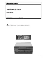
Page 1: ...1 TravelPilot RGN 08 7 612 001 147 Installation notes for authorired service workshopsIn 8 622 401 437 GB 3 98 7 612 001 147 8 622 401 437 02 98...

Page 2: ...s 3 Important instructions for connecting the speedometer signal 4 Connecting the speedometer signal 4 Connecting the back up light signal cable 4 Distance calibration 4 Installing the wheel sensor an...

Page 3: ...ards and backwards by evaluating the back up signal forwards 0 volts backwards 12 volts received via the connection contact RFLS provided for that purpose Because of the integrated gyro and CD ROM dri...

Page 4: ...le item 8 to the vehicle s spe cific car radio jack Connecting the back up light signal cable Important Only an authorised customer service centre should make this connection The connection is made wi...

Page 5: ...que re commended by the factory Lay the sensor wires into the interior of the vehicle use any existing bushings or drill new holes and lay them to the navi gation unit Installation tolerances for the...

Page 6: ...ys to move the cursor to the desired digit and press S to confirm Repeat this process until the appropriate distance value is shown in the display in this example 160 0 m 4 Now keep the S key depresse...

Page 7: ...cm 5 8 618 841 412 DC cable 6 m 6 8 618 842 033 Reversing light cable 4 5 m RFLS 7 8 618 841 988 Speedometer signal cable 4 5 m 8 618 842 265 Can adapter wiring 8 618 841 525 Can cable 6m 8 618 841 4...

Page 8: ...Stand by current Typically 0 35 A Speech output volume Max 3 Watt 4 Ohm Time to first position computation Warm start memory refresh 2 minute cold start memory clear 15 minutes CD ROM drive For 12 cm...

Page 9: ...9 Fig 1 Fig 4 Fig 2 Fig 3 8 622 401 437...

Page 10: ...rim 8 618 841 475 1 5 m Magnetic strip Interface 12 7 mm 2 914 551 015 Magnetic strip max 10 Sensor middle Z Y Fig 13 Fig 12 10 90 mm Fig 15 Fig 16 Fig 14 Fig 17 Z 5 mm Z 8 mm Z 12 7 mm Fig 18 Magnet...

Page 11: ...sensor g e w Sped impuls br rt KL 30 sw KL 15 12V 10 10 Kl 30 Info IN RC 07 8 622 401 437 Navigationsgrundger t 8 618 841 994 cinch cable NF 6m can cable can adapter cable Bremen New York g e 4 5 m 4...

Page 12: ...12 8 622 401 437 6m 6m Opto CDC F07 1 0A Bremen New York Kl 30 12V NF Navi CDC F07 RC 07 RC 07 RGN 08 RGN 08 CDC F07 RC 07 can cable 6m or 2m connection wiring CDC Fo7 Subject to modification...

Reviews: