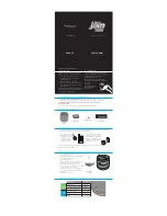
Functions
1. MAINS SWITCH: Turns the system on and off. Ensure the level controls are at minimum when
switching on and off.
2. RGB LIGHT SWITCH: Turns the system on and off. Ensure the level controls are at minimum when
RGB LIGHT switching on and off.
3. MAINS INLET SOCKET AND FUSE: IEC input for connection of an appropriate mains lead.
4. Antenna for wireless microphone use
5. MASTER VOLUME: Controls the overall level of your equipment.
6. MP3 / LINE VOLUME: Control the MP3 and LINE Level of your equipment.
7.
AUX IN :
Please use a stereo cable connect.
8. RCA (R+L) Line Output
9. RCA (R+L) Line Input
10. LINE INPUT: An unbalanced input - for higher output line level devices eg. - keyboard, processor,
drum machine.
11. MIC/LINE INPUT:
MIC: a balanced input for low level, low impedance devices eg. -mic (200-600ohms) or electro acoustic
guitar.
LINE: a balanced input for higher output line level devices eg. -sub or mixer.
12. ECHO : For Microphone Echo Volume
13. MP3 Switch: It allows to switch on /off the MP3 player and Line In.
14. Wireless microphone MIC1 Volume control
15.
MIC2 Volume control
16. GRAPHIC EQUALIZER Control
17. MODE: Select the input source - SD card USB or Bluetooth
18. PLAY/PAUSE: Use this control to play or pause your MP3 music/backing track.
19. LOOP: Use this to enable/disable the looped playback modes. When using this button with an SD
card or USB Stick, there are 4 options:
ALL - Plays all the tracks on the root of the device in date order, then the sub folders
FOLDER - Plays all the tracks in the chosen folder
ONE - Plays one track repeatedly (cycle to the required track to play using NEXT button (20).
RANDOM - Plays tracks randomly
20. PREVIOUS: Press to skip to the preceding track.
21. NEXT: Press to skip to the next track.
22. SD CARD SLOT: Insert your standard SD card here. (Automatically detected on insertion, or if
removed & reinserted uses smart technology to resume play from the previous point).
23. Pair. Press the pair button to enable Bluetooth pairing, it should now be visible to your bluetooth
device.
24. TWS. The TWS (True Wireless Stereo) button is used to link two cabinets together. Press TWS on
the first cabinet, the led flashes blue/green. press the TWS button on the second cabinet, they will find
each other and the led changes to blue followed by a confirmation noise. The cabinets are now linked and
anything played via Bluetooth, or on the media player will be sent to both speakers. Hold the TWS button
to unlink the device.


