background image

KoMFort erv d

8

www.blaubergventilatoren.de

DESIGN AND OPERATING PRINCIPLE

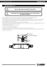
Supply fan

Extract fan

Extract air filter

Control unit

Thermostat for heat exchanger freeze protection

Cable glands

Cross-flow heat exchanger

Supply air filter

Controller

Power cord with a plug

Inspection hatch for filter and heat

exchanger maintenance

Left-handed modification

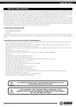
The service side of the unit is equipped with a detachable inspection hatch on manual bolts for filter and heat exchanger cleaning and 
replacement operations. The plate enthalpy cross-flow heat exchanger is made of polymerized cellulose. 
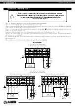
The control unit is positioned inside the unit casing . The power cable and grounding cables are connected to the control unit via the 
cable gland located at the side of the unit. The unit is equipped with a controller and a power cord with a Euro Plug XP. 
Warm stale extract air from the room flows into the unit, where it is filtered by the extract filter, then air flows through the heat 
exchanger and is exhausted outside by the extract fan. Cold fresh air from the outside flows into the unit, where it is cleaned by the 
supply filter. Then the air flows through the heat exchanger and is directed to the room with the supply fan. 
Supply air is heated in the heat exchanger by transferring the heat energy of warm and humid extract air to the cold fresh air.
The air flows are fully separated while flowing through the heat exchanger. Heat recovery minimizes heat losses, which reduces the 
cost of space heating in the cold season. The enthalpy heat exchanger provides both heat and humidity recovery.  
In warm seasons the heat exchanger operates to cool down and dehumidify the supply air. In cold seasons the heat exchanger 
operates to warm up supply air and humidify it. Water vapour from the humid extract air is condensed and absorbed by the heat 
exchanger plates. The recovered humidity and heat are transferred to the supply air flow. The air streams are fully separated within the 
heat exchanger and the microbes and smells are isolated.

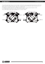
LEFT-HANDED AND RIGHT-HANDED MODIFICATIONS

The figure below shows the arrangement of spigots for left- and right-handed modifications. Choosing the right arrangement can 
improve the ease of installation, shorten the length of the ducts and reduce the number of air duct bends (elbows)

R

EXTRACT AIR

SUPPLY AIR

INTAKE AIR

EXHAUST AIR

INTAKE AIR

SUPPLY AIR

EXHAUST AIR

EXTRACT AIR

Left-handed modification

Right-handed modification

Summary of Contents for KOMFORT ERV D 100

Page 1: ...Heat and energy recovery air handling unit USER S MANUAL EN KOMFORT ERV D 100 KOMFORT ERV D 200 KOMFORT ERV D 300 KOMFORT ERV D 450...

Page 2: ...ractical training in the field of ventilation systems and should be able to work in accordance with workplace safety rules as well as construction norms and standards applicable in the territory of th...

Page 3: ...ospheric agents rain sun etc Transported air must not contain any dust or other solid impurities sticky substances or fibrous materials Do not use the unit in a hazardous or explosive environment cont...

Page 4: ...f the supply cord is damaged it must be replaced by the manufacturer its service agent or similarly qualified persons in order to avoid a safety hazard Ensure that the unit is switched off from the su...

Page 5: ...ltered stream of intake air The unit is not intended for organizing ventilation in swimming pools saunas greenhouses summer gardens and other spaces with high humidity Due to the ability to save heati...

Page 6: ...ample of new buildings The unit is rated as a Class I electrical appliance Hazardous parts access and water ingress protection rating IP22 for the unit connected to the air ducts IP44 for the unit mot...

Page 7: ...D B L L A B A B Model Dimensions mm D A A1 B B1 H H1 L KOMFORT ERV D 100 100 734 600 481 571 204 223 300 KOMFORT ERV D 200 100 987 854 704 793 222 241 480 KOMFORT ERV D 300 150 987 854 704 793 227 246...

Page 8: ...hen the air flows through the heat exchanger and is directed to the room with the supply fan Supply air is heated in the heat exchanger by transferring the heat energy of warm and humid extract air to...

Page 9: ...s 3 After temperature increase the unit returns to the previous operation mode In the Defrosting mode the supply fan is turned off and the heat exchanger is warmed up with warm extract air flow To set...

Page 10: ...alist Before mounting make sure the casing does not contain any foreign objects e g foil paper The minimum distance between the unit and the ceiling should be at least 20 mm To attain the best perform...

Page 11: ...t label It is recommended to select the nominal current of the circuit breaker from the standard series following the maximum current of the connected unit The circuit breaker is not included in the d...

Page 12: ...nce a year Some dust may accumulate on the heat exchanger block even in case of regular maintenance of the filters To maintain high heat exchange efficiency periodical dry cleaning is recommended Use...

Page 13: ...and mechanical damage The unit must be transported only in the working position Avoid sharp blows scratches or rough handling during loading and unloading Prior to the initial power up after transpor...

Page 14: ...the Seller for warranty service The manufacturer s warranty does not apply to the following cases User s failure to submit the unit with the entire delivery package as stated in the user s manual inc...

Page 15: ...RTIFICATE The _____________________________________ unit is installed pursuant to the requirements stated in the present user s manual Installation Stamp Company name Address Phone Number Installation...

Page 16: ...www blaubergventilatoren de B147 1EN 02...

Reviews: