


www.blaubergventilatoren.de
KoMFort roto ec S6(e)K 200
13
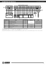
EXTERNAL WIRING DIAGRAM
XS11
X1
1
C
2
NC
3 4
N
5
L
Grey
Black
Yellow/green
Blue
Brown
KH1*
TS1
1
2
1
2
HL
PE
GND
GND 0-10V
A
B
+24V
+24V
1
2
PK1*
1
2
1
2
1
2
1
2
Boost*
CO2*
P1*
SM1*
SM2*
1
2
C
C
U
*
1
2
1
2
**U
**U
L
N
N
NC C
PE
L
C
NO
NO
NO
C
C
C
A B
0-10V +24V
+24V
NO
GND
GND
1 2 3 4 5 6 7 8 9 10 11 12 13 14 15 16 17
Po
wer supply
230
V, 50 H
z
Brown
Yello
w
Gr
een
W
hit
e
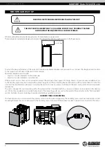
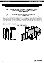
Electric shock hazard!
Designation
Name
Contact type
Cable type
Note
SM1*
Supply air damper actuator
NO
2 x 0.75 mm
2
3A, 30DC/~250 AC
SM2 *
Extract air damper actuator
NO
3A, 30DC/~250 AC
PK1*
Contact from fire alarm panel
NC
Remove the jumper
CCU*
CCU control
NO
3A, 30DC/~250 AC
P1*
External control panel
4 x 0.25 mm
2
Boost*
On/Off contacts of the Boost mode
NO
2 x 0.75 mm
2
CO2*
Outdoor CO
2
sensor
3 x 0.25 mm
2
KH1*
Kitchen hood
5 x 0.75 mm
2
*Is not included in the delivery set.
*The supply voltage U of the SM1, SM2 external dampers is selected depending on the type of dampers.
Output parameters: terminals 12-17 - 3 A, 30VDC / ~ 250VAC (“dry contact”).
The maximum cable length from external devices to the terminal block should not exceed 100 meters. The recommended cable cross-section is shown in the table.