


www.blaubergventilatoren.de
vento eco(2) a50-4 Pro
11
CONNECTION TO POWER MAINS AND CONTROL
POWER OFF THE POWER SUPPLY PRIOR TO ANY OPERATIONS WITH THE UNIT.
THE UNIT MUST BE CONNECTED TO POWER SUPPLY BY A QUALIFIED ELECTRICIAN.
THE RATED ELECTRICAL PARAMETERS OF THE UNIT ARE GIVEN ON THE
MANUFACTURER’S LABEL.
ANY TAMPERING WITH THE INTERNAL CONNECTIONS IS PROHIBITED
AND WILL VOID THE WARRANTY.
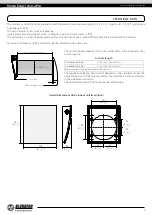
The ventilator is rated for connection to single-phase AC 100-240 V/50 (60) Hz power mains.
The ventilator is connected to power mains using insulated, durable and heat-resistant conductors (cables, wires) with a cross section of
at least 0.5-0.75 mm2 through the automatic circuit breaker with a magnetic trip built into the stationary wiring. The circuit breaker trip
current must be selected depending on the ventilator current consumption. For details, please refer to the table on page 5.
The actual conductor cross-section selection must be based on its type, maximum permissible heating, insulation, length and installation
method.
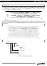
When choosing a signal cable, follow these guidelines:
• Always use a shielded cable.
• The cross-section of the conductors, depending on the length, is selected according to the table below.
Cable length [m]
T
he minimum cross-section of the wires in the cable [mm2]
<
5
0.25
<
10
0.5
<
15
0.75
<
30
1.5
• Lay a signal cable in compliance with the requirements of the relevant regulatory documents.
• Connect the signal cable shield to the terminals „-“ of the control panel and the fan. Use copper wires for all the electric
connections!
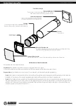
• Connect the ventilator to power mains in compliance with the wiring diagram.