


www.blaubergventilatoren.de
vento expert (Duo) a50(30)-1 Pro/Pro3
14
POSITIONING OF THE DIP SWITCHES
1
Turning the ventilator off is allowed
. The switch position enables switching the ventilator off with the button on the
side control panel.
1
Turning the ventilator off is not allowed.
The switch position disables switching the ventilator off with the button on
the side control panel.
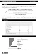
Vento Expert A50-1 Pro/Pro3
Vento Expert Duo A30-1 Pro
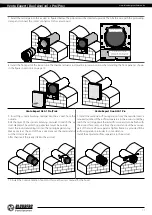
Fan rotation direction.
For controlled ventilation it is
recommended to install the ventilators pairwise and integrate
them in a group using a signal cable. Set one half of the
connected units into supply mode and the other half into extract
mode.
Boost mode setup.
When the humidity sensor or the external
relay is triggered, one of two operation algorithms starts.
2
In the Ventilation mode the ventilator supplies the air
to the room.
In the Regeneration mode the ventilator starts
operating first in supply mode.
2
OFF:
the ventilator runs in the extract mode at the
third speed (both fans run in the extract mode).
2
In the Ventilation mode the ventilator extracts the air
from the room.
In the Regeneration mode the ventilator starts
operating first in extract mode.
2
ON:
the ventilator switches to maximum speed
without changing the operation mode.
Humidity sensor set value.
The humidity sensor measures the extract air humidity. If the extract air humidity is above the set point, the
ventilator switches to Speed III. As humidity drops down to the set point, the ventilator changes to pre-set speed after elapsing of the
time set on the turn-on delay timer.
Humidity control is
disabled
Set value 40 %
Set value 50 %
Set value 60 %
Set value 70 %
Set value 80 %
3
4
5
3
4
5
3
4
5
3
4
5
3
4
5
3
4
5
Delay timer.
During activation of the humidity sensor or any other external device the ventilator switches to higher speed. After
normalization of the indoor humidity level or any other air parameters the ventilator will switch to the previous mode after the set time.
Time delay 0 min
Time delay 5 min
Time delay 15 min
Time delay 30 min
6
7
6
7
6
7
6
7
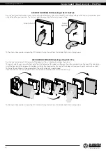
VENTILATOR CONTROL
The ventilator can be operated with the remote control or the control buttons on the side part of the indoor unit, as figured below.
In case of in series or in parallel connection, the signal from a control unit is received by the first ventilator (Master) only.
Turning
the ventilator on/off
Party mode
Activation of Speed III by the timer
(4 hours by default).
Night mode
Activation of the Speed I by the timer
(8 hours by default).
Speed selection
Speed/Standby
The speed selection sequence is as
follows: I-II-III-Standby
Regeneration mode
Every 70 seconds the ventilator
changes the fan rotation direction to
opposite. Heat recovery is performed
in this mode.
Ventilation mode
The ventilator operates either in the
extract or supply mode at a set
speed.
Remote control
Buttons on the
ventilator casing
Alarm indicator
In case of the motor jam, the Alarm
indicator starts glowing and the
ventilator stops. All the ventilators
connected in series stop
synchronously.
Master indicator
Indicator of the first ventilator in the
group.
Filter indicator
After the set filter replacement
periodicity (90 days) has expired, the
Filter indicator starts glowing. In this
case clean or replace the filters.