


520-319-000 Air Operated Double Diaphragm Pump 11/01
PUMPING HAZARDOUS
LIQUIDS
When a diaphragm fails, the
pumped liquid or fumes enter the
air end of the pump. Fumes are
exhausted into the surrounding
environment. When pumping haz-
ardous or toxic materials, the ex-
haust air must be piped to an ap-
propriate area for safe disposal. See
illustration #1 at right.
This pump can be submerged if
the pump materials of construction
are compatible with the liquid being
pumped. The air exhaust must be
piped above the liquid level. See
illustration #2 at right. Piping used
for the air exhaust must not be
smaller than 1" (2.54 cm) diameter.
Reducing the pipe size will restrict
air flow and reduce pump perfor-
mance. When the pumped product
source is at a higher level than the
pump (flooded suction condition),
pipe the exhaust higher than the
product source to prevent siphon-
ing spills. See illustration #3 at right.
IMPORTANT INSTALLATION
NOTE:
The manufacturer recom-
mends installing a flexible hose or
connection between the pump and
any rigid plumbing. This reduces
stresses on the molded plastic
threads of the air exhaust por t.
Failure to do so may result in
damage to the air distribution valve
body.
Any piping or hose connected to
the pump’s air exhaust port must be
physically supported. Failure to
support these connections could
also result in damage to the air
distribution valve body.
SAFE AIR
EXHAUST
DISPOSAL
AREA
PUMP INSTALLATION AREA
1" DIAMETER AIR
EXHAUST PIPING
SILENCER
CONVERTED EXHAUST ILLUSTRATION
Illustration #1
Illustration #2
Illustration #3
1" DIAMETER AIR
EXHAUST PIPING
LIQUID
LEVEL
SUCTION
LINE
SILENCER
1" DIAMETER AIR
EXHAUST PIPING
LIQUID
LEVEL
SUCTION
LINE
SILENCER
Page 10
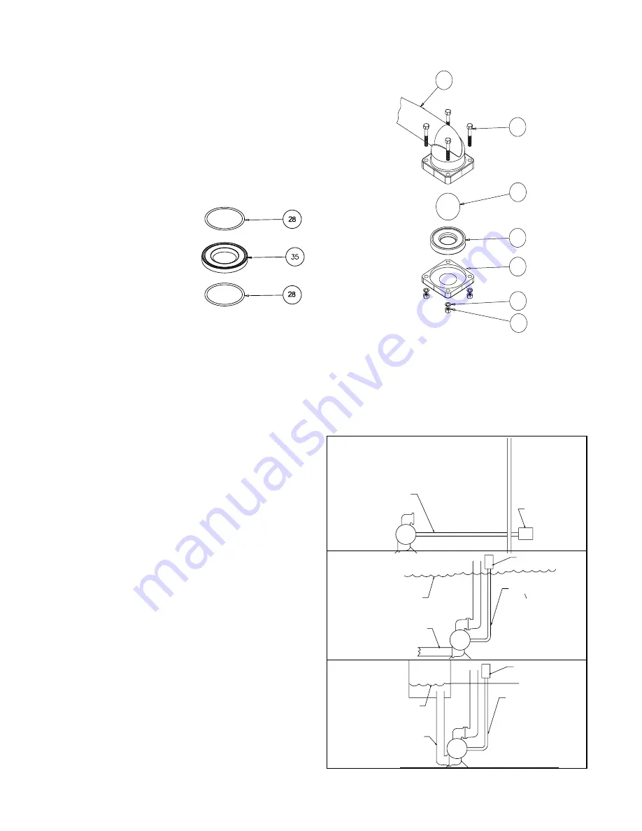
Check Valve Drawing
CHECK VALVE SERVICING
Before servicing the check valve
components, first shut off the
suction line and then the discharge
line to the pump. Next, shut off the
compressed air supply, bleed air
pressure from the pump, and dis-
connect the air supply line from the
pump. Drain any remaining fluid from
the pump. The pump can now be
removed for service.
To access the check valve
components, remove the manifold
(item 23 or item 22 not shown). Use
a
5
/
8
" &
11
/
16
" wrench or socket to re-
move the fasteners. Once the mani-
fold is removed, the check valve
components can be seen.
Inspect the check balls (items 2)
for wear, abrasion, or cuts on the
spherical surface. The check valve
seats (item 35) should be inspected
for cuts, abrasive wear, or embed-
ded material on the surfaces of both
the external and internal chambers.
The spherical surface of the check
balls must seat flush to the surface
of the check valve seats for the pump
to operate to peak efficiency.
Replace any worn or damaged parts
as necessary.
Reassemble the check valve
components. The seat should fit
into the counter bore of the outer
chamber.
23
10
2
35
14
36
25
with Non-Metallic
Seats
with Metallic Seats
The pump can now be reas-
sembled, reconnected and returned
to operation.
METALLIC SEATS
Two o-rings (or seals) (item 28)
are required for metallic seats.
Summary of Contents for B75
Page 2: ......