BLACKMER SMVP15C Instructions Manual Download Page 4

108-A00: Page 4/12 

INSTALLATION 

MOTOR INSTALLATION 


Strong magnetic field can cause 
personal injury or death to individuals 
with medical implants or other magnetic 
field sensitive medical conditions 


Strong  
Magnetic  
field 


Failure to use care when handling 
magnets can cause personal injury 

Strong magnetic 
field can cause 
personal injury 


NOTICE:


Clear work area of all tools and materials affected by 
magnets.  Non-magnetic work surface recommended. 

MAGNET SET 

1.  Put drive key in keyway on motor shaft. 

2.  Loosely assemble bushing with bolts & outer magnet. 

Slide magnet assembly onto motor shaft. 

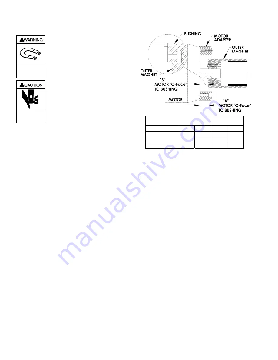
3.  Position bushing and magnet to Reference Dim “B”,  

(see Table 1) and tighten setscrew over drive key.   

4.  Tighten the 3 bolts in a uniform sequence, torque to 9 ft 

lbs. (12.2Nm) 

5.  When bolts are tightened, take a measurement for Dim 

“A”. (see table 1) 


Table 1 

Dim “A”  

Magnet Set 

Dim “B” 

Bushing Set 

Motor Frame


INCH MM INCH MM 

143TC / 145TC 

0.464 

11.8 

0.454 

11.5 

182TC / 184TC 

1.274 

32.4 

1.264 

32.1 

213TC / 215TC 

1.374 

34.9 

1.364 

34.6 

6.  If Measurement “A” does not match the value in the Table, 

the bushing 

MUST

 be repositioned with a new Dim “B”. 

Loosen the bolts and setscrew. 

If Measurement “A” is 

High:


Move the bushing towards the motor “C-Face” 
New Dim “B” = table Dim “B” less the difference 
between Measurement “A” and table Dim “A”. 

If Measurement “A” is 

Low

Move the bushing away from the motor “C-Face” 
New Dim “B” = table Dim “B” plus the difference 
between Measurement “A” and table Dim “A” 

7.  Retighten setscrew over drive key.  Repeat Steps 4 – 6 

8. 

When Dim “A” is set correctly.

  Ensure that Shaft & 

Outer Magnet assembly rotate freely without binding  

9.  Slide the motor adapter ring (86) over the outer magnet to 

the “C-Face” of the motor.  Ensure that the flange of the 
motor adapter ring is fully and squarely seated.  Install the 
adapter ring capscrews (56) torquing to 40 lbs ft (54 Nm) 

NOTICE: 

Be prepared for strong magnet attraction between the 
inner and outer magnets, forcibly pulling the motor 
coupling adapter assembly inward. 

10.  Ensure that the magnet housing (57) is bolted to the base. 

11.  Using an appropriately sized hoist, CAREFULLY insert the 

outer magnet and motor into the mounted magnet housing 
(57).  

12.  With the magnet housing fully and squarely seated, install 

the four housing capscrews (54B); torque to 40 lbs ft (54 
Nm). 


Figure 3

Summary of Contents for SMVP15C

Page 1: ...t or in the manual look for one of the following signal words and be alert to the potential for personal injury death or major property damage Warns of hazards that WILL cause serious personal injury death or major property damage Warns of hazards that CAN cause serious personal injury death or major property damage Warns of hazards that CAN cause personal injury or property damage NOTICE Indicate...

Page 2: ...ump operation can cause serious personal injury death or major property damage Hazardous pressure can cause personal injury or property damage Operation without coupling guard can cause serious personal injury death or major property damage Do not operate without guards in place PUMP DATA PUMP IDENTIFICATION A pump Identification tag containing the pump serial number I D number and model designati...

Page 3: ...t be cleaned regularly to avoid pump starvation 5 Intake and discharge piping MUST be free of all leaks 6 Expansion joints placed at least 36 0 9m from the pump will compensate for expansion and contraction of the pipes Contact the flexible connector hose manufacturer for required maintenance care and design assistance in their use 7 Install vacuum and pressure gauges in the 1 4 NPT ports provided...

Page 4: ...h the value in the Table the bushing MUST be repositioned with a new Dim B Loosen the bolts and setscrew If Measurement A is High Move the bushing towards the motor C Face New Dim B table Dim B less the difference between Measurement A and table Dim A If Measurement A is Low Move the bushing away from the motor C Face New Dim B table Dim B plus the difference between Measurement A and table Dim A ...

Page 5: ...etting of the pump relief valve by gradually closing a valve in the discharge line momentarily and noting the reading on the pressure gauge This pressure reading should be 10 20 psi 96 1 4 bar higher than the maximum system operating pressure DO NOT run the pump for more than 15 seconds with the discharge valve completely closed If adjustments need to be made refer to Relief Valve Setting and Adju...

Page 6: ...st a closed discharge valve RELIEF VALVE SETTING AND ADJUSTMENT The factory relief valve pressure setting is marked on a metal tag attached to the valve body It is recommended the relief valve be set at least 10 20 psi 69 1 4 bar higher than the operating pressure or the system pressure control valve setting DO NOT remove the R V Cap OR adjust the relief valve pressure setting while the pump is in...

Page 7: ...peration without guards in place can cause serious personal injury major property damage or death Do not operate without guard in place Disconnecting fluid or pressure containment components during pump operation can cause serious personal injury death or major property damage Hazardous pressure can cause serious personal injury or property damage Failure to use care when handling magnets can caus...

Page 8: ...the magnet housing 5 Remove the containment can 50 from the inboard head using a slight pry if necessary DO NOT damage the containment can or pump head Remove and discard the containment can O ring 51 Failure to use care when handling magnets can cause personal injury Strong magnetic field can cause personal injury 6 With properly sized snap ring pliers remove the snap ring 83 from the shaft end P...

Page 9: ... press remove the old bearing from the head b To aid installation and prevent damage heat the head in an oven to 200 F 93 C c Coat the new bearing with a quality grade of bearing grease and place it on the inside face of the head with the notched end UP Align the notch in the bearing with the groove in the head d Using an arbor press CAREFULLY press the bearing into the head until it is flush with...

Page 10: ...n the inboard shaft end 2 Align the inner magnet 52 with the key and slide the magnet over the shaft with the pump end of the magnet towards the inboard head 3 Fully and squarely install the snap ring 83 into the groove in the end of the shaft 4 Check to ensure the pump shaft rotates freely when turned by hand 5 Install a new containment can O ring 51 into the groove provided on the hub of the inb...

Page 11: ...e incorrectly set 2 Leaks in suction piping 3 Incorrect rotation 4 Broken shaft 5 Pump vapor locked 6 Incorrect pump speed 7 Vanes damaged worn or incorrectly installed 8 Cavitation 9 Damaged or worn pump or system components 10 Excessive piping system friction losses 11 Relief valve incorrectly set worn or damaged 12 Operating against a closed discharge 13 Shaft bent or misaligned 14 Worn or dama...

Page 12: ...n 49503 1530 U S A Telephone 616 241 1611 Fax 616 241 3752 Email blackmer blackmer com Internet www blackmer com Дистрибутор ОПВ Маркет ЕООД България София 1528 ул Поручик Неделчо Бончев 3 eт 5 тел 02 973 27 67 e mail office_bg opwmarket com ...

Reviews: