background image

6

www.digiop.com

SECTION 2: INSTALLATION AND SETUP

NOTE:

 When connecting leads from external devices 

to the terminal block, use the pin definitions shown on 

the circuit board as a guide. Pin definitions on the circuit 

board may be different from those shown below. 

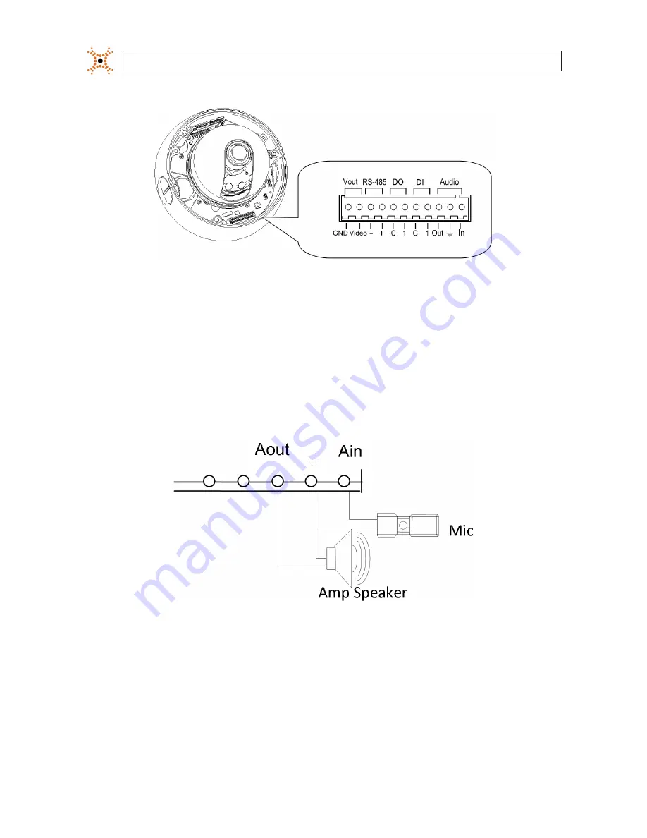
Terminal block pin assignments

The 11-pin terminal block may be detached from the camera. Install the block in the location shown above. 

2.4.1  Audio in/out connections

The camera includes an interface for a mono audio input (from a microphone) and a mono audio output (to a speaker). The audio 
output is a low level signal that requires an amplified speaker (see Specifications). The configuration of the audio wiring (Aout, Ain) 
is shown in the diagram below. 

Audio in/out wiring schematic

To connect a speaker and/or microphone to the camera: 

1. 

Route speaker and/or microphone wiring through the cable channel and into the camera base housing. 

2. 

Strip 1/4” of insulation from the wires and insert them into the terminal block in the locations shown connector terminal 
figure above. The common (ground) leads to the microphone and speaker share the same terminal block pin. 

Summary of Contents for BLK-IPD102

Page 1: ...i Dome IP Camera User Manual Product BLK IPD102 Please read this manual before using your camera and always follow the instructions for safety and proper use Save this manual for future reference BLK...

Page 2: ...s of others without their knowledge and or consent We encourage you to check and comply with all applicable local state and federal laws and regulations before engaging in any form of surveillance or...

Page 3: ...camera network settings 10 2 6 1 Configuring cameras on networks with DHCP 11 2 6 2 Configuring cameras on networks without DHCP 13 2 7 Setup the camera Basic Configuration 18 2 8 Aim focus and image...

Page 4: ...ing on DSP Unicast multicast support H 264 MPEG4 MJPEG 25 30 fps D1 G 711 Law aLaw PCM audio compression 2 way mono audio support RTSP HTTP protocol support 10 100 Base T Ethernet support RS485 suppor...

Page 5: ...al this document 2 2 Tools you need To install the camera you will need Phillips 2 screwdriver PC with Microsoft Windows XP SP3 or newer 32 or 64 bit system Depending on how the camera is mounted you...

Page 6: ...rew holes into the surface before attaching the camera 5 Determine the extension cable routing If the cable is to be routed through the hole in the bottom of the base perform the following steps If th...

Page 7: ...the cable port in the bottom of the base 12 Install a conduit fitting onto the side of the base 13 Place the base seal over the base aligning the holes for the mounting screws in the base with those i...

Page 8: ...e for a mono audio input from a microphone and a mono audio output to a speaker The audio output is a low level signal that requires an amplified speaker see Specifications The configuration of the au...

Page 9: ...ws a maximum input of 24 V DC with a 1 V DC threshold see Specifications The configuration of the sensor input wiring is illustrated in the diagrams below CAUTION Donotexceedthemaximuminput voltageort...

Page 10: ...trated in the diagram below CAUTION Donotexceedthemaximumrelayrating Refertothespecifications in thismanual for more information Relaytypealarmwiringschematic To connect an alarm reporting device to t...

Page 11: ...shown in the schematic 2 4 5 Video out connection The camera provides pins on the terminal block to attach a local video monitor A cable extension with a BNC connector is included in the packaging wit...

Page 12: ...rdware adjustments and configure the camera for functional requirements The IPAdminTool can be loaded on a Microsoft Windows XP Vista or Windows 7 operating system 32 or 64 bit To use this utility for...

Page 13: ...ings for your camera If connecting your camera to a large enterprise network consult with your network administrator for network settings before attaching the camera to the LAN to ensure that your cam...

Page 14: ...he Refresh button every minute until your camera appears in the list 3 In the IPAdmin Tool device list use the camera s MAC Address to find the camera you are installing After finding the camera right...

Page 15: ...ory default static network settings IP address 192 168 0 100 Subnet mask 255 255 255 0 Gateway 192 168 0 1 In networks without a DHCP server cameras must be powered on and reconfigured one at a time t...

Page 16: ...k and Default Gateway for your PC s Ethernet adapter into Table 1 NOTE TheEthernetadapterdatayouseebyusing ipconfigwill probablybedifferent from thatshown in the example above IfyouareusingWindowsVist...

Page 17: ...00 c Next use the ping command in the DOS window to see if this IP address is in use on your network The format of the ping command is ping IP address To test this IP address enter ping 192 168 1 200...

Page 18: ...subnet where the camera will be connected open a Command Prompt window and enter ping 192 168 0 100 The Request timed out response indicates that the IP address is not in use and the camera can be co...

Page 19: ...if it is not selected This option is required if video from the camera will be recorded by a network DVR or if you want to view video from the camera across a WAN Internet b Enter the IP address for...

Page 20: ...e camera administrator and user passwords date and time 1 Open the IE browser 2 In the URL field Internet address enter the IP address for your camera in the format http IP address where IP address is...

Page 21: ...eMSXML4 0library Thislibrarycan be foundat http www microsoft com downloads details aspx familyid 3144B72B B4F2 46DA B4B6 C5D7485F2B42 displaylang en 4 In the camera window click the SETUP link in the...

Page 22: ...Time Setting options a Select the Time Zone you prefer b Select the synchronization method or Set Manually bullet and enter the appropriate information c Select the Sync Source and Interval you prefe...

Page 23: ...tor user with a new password and click OK 8 In the Users menu click Apply then click OK to restart the webserver if you wish to do so at this time 9 Click Add to include other administrators operators...

Page 24: ...dule bracket on its horizontal axis direction the lens is pointed 3 Set the horizontal direction of the video frame by rotating camera assembly on its vertical axis 4 Set the up down position of the v...

Page 25: ...NSTALLATION AND SETUP 5 Reinstall the camera dome 2 8 3 Image quality adjustments Adjustments to the image brightness contrast hue saturation and sharpness are performed through the web browser 1 From...

Page 26: ...video image 4 Close the PREVIEW window and click VIEW to return to the normal viewing window 2 9 Speaker microphone setup NOTE Amicrophoneandspeakerarenotsupplied withthiscamera Verify the functionali...

Page 27: ...adjust the speaker volume go to the Bi directional Audio Settings menu In the Talk to frame adjust the volume to an appropriate level Click Apply 2 10 Cleaning Clean the camera housing with an approv...

Page 28: ...AUTO AGC Control OFF LOW MIDDLE HIGH selectable White Balance ATW AWC MANUAL 1 800 K 10 500 K Electronic Shutter Speed AUTO MANUAL X256 1 60 sec 1 120 000 sec Sense up and Sense up Limit is selectabl...

Page 29: ...1 49 Vp p 39 K Audio Output Lineout 46 mW Power 16 Sensor D I TTL level 4 5V threshold Max 50 mA Alarm D O Max 500 mA 24 V AC or 1A 12 V DC Power Source Approx 12 V DC 300 mA or PoE IEEE 802 3af Class...

Page 30: ...and enter the administrator ID and PW d Click Refresh to re discover the camera Using the reset button on the camera a Press and hold the reset button on the camera for 5 seconds b Click Refresh to r...

Page 31: ...upport for firmware updates A 4 Support If you cannot resolve an issue please contact the DIGIOP Support at 1 877 972 2522 for assistance When you contact support please provide the server reports log...

Page 32: ...30 www digiop com APPENDIX B DIMENSIONS APPENDIX B Dimensions 5 94 6 02 4 45 3 94...

Page 33: ...voltage range and provides a regulated low ripple and low noise output The AC DC converter also has built in overload and short circuit output protection C 1 PoE compatibility With non Power Sourcing...

Reviews: