


4
SECTION 2: INSTALLATION
SECTION 2
Installation
2.1 General Guidelines
•
The camera drop cable connects to the network cables (RS-485, alarm in/out, HD-SDI video out, 24 Vac power leads) inside
the mounting bracket provided with the camera. A cable access cover on the underside of the mounting bracket allows access
to cable connections, and to the composite video monitoring drop.
•
Network cables can be routed into the mounting bracket through conduit attached to the underside of the mounting bracket,
or through the mounting bracket mounting.
•
Hardware configuration switches (for camera ID, video mode, RS-485 protocol, etc.) are accessible when the camera dome
cover is removed.
•
Position the camera in a location where it provides the best visibility of your surveillance targets, and is difficult to tamper with
or damage.
•
Use extra care to avoid damaging the camera dome cover.
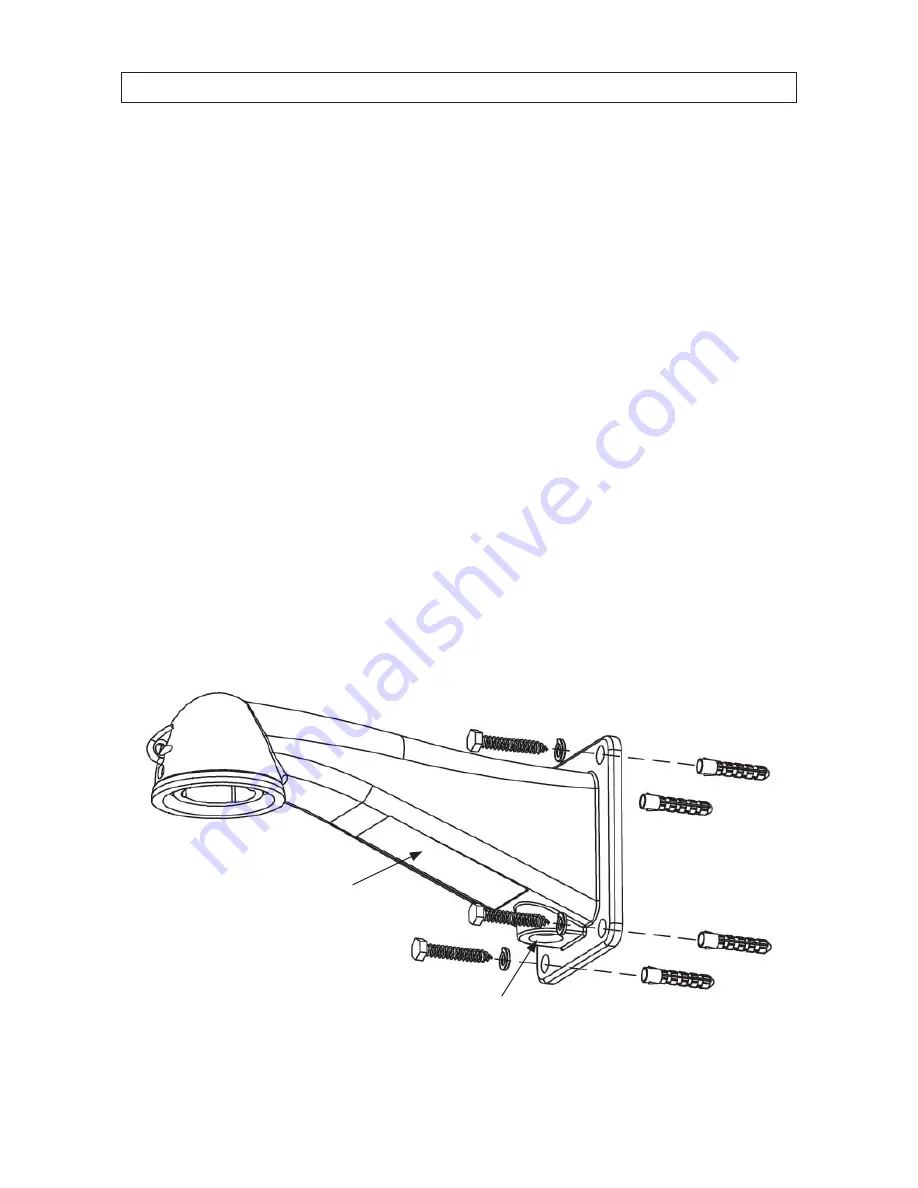
2.2 Install the mounting bracket
1.
Using the mounting bracket as a template, mark the location of the mounting screw/wall anchor holes. Although bolts,
washers and wall anchors are included with the camera, these may not be appropriate for the surface where the bracket will
be attached. Always use the appropriate mounting hardware to ensure that the bracket is securely attached to the mounting
surface.
Mounting bracket
Cable access
cover
Conduit
connector
Wall anchor
Bolt and washer
Summary of Contents for BLK-HDPTZ12
Page 6: ...vi NOTES ...
Page 44: ...38 SECTION 4 OSD MENU STRUCTURE REFERENCE 4 2 DISPLAY SETUP submenus ...
Page 52: ...46 ...


