
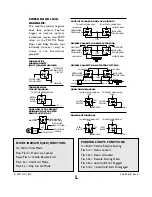

If the Current Sense feature of the remote start
unit does not allow proper operation, the tach
sense/spark sense wire may be used, or an optional
vacuum switch can be installed.
To use the tach sense/spark sense wire, set dip
switch #1 to the off position. Connect the GREEN
wire directly to the vehicle’s tach wire or extend it
into the engine compartment and wrap it several
times around a spark plug wire or coil wire.
In situations were a tach wire is unavailable or does
not allow proper operation, an optional vacuum
switch can be installed. The vacuum switch is
designed to be placed in line with one of the
vehicle’s vacuum hoses and provide a ground
output until the engine is started.To use the vacuum
switch, set dip switch #2 to the off position.
Connect the YELLOW wire, from accessory plug,
to one terminal of the vacuum switch and connect
the other terminal to ground.
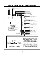
High-Current Wire Connections:
• RED WIRE #1 -Main power input; using the
supplied inline fuse holder, connect directly to the
vehicle’s battery or alternate power source with a
minimum 30 Amp supply.
• RED WIRE #2 - Secondary power input; using
the supplied inline fuse holder, connect directly to
the vehicle’s battery or alternate power source
with a minimum 30 Amp supply.
Note: If not connecting directly to the vehicle’s
battery, it is recommended to use separate power
sources (minimum 30 Amp each) for each red
power wire.
• BROWN WIRE - Second ignition output;
connect to the wire that sw12 V and does
not drop out during cranking (may be optionally
programmed to function as a second accessory
output - see Programmable Features).
• YELLOW WIRE - Main ignition output; connect
to the main ignition wire that sw12 V and
does not drop out during cranking.
• ORANGE WIRE - Main accessory output; This
pr12V output to heater and/or air
conditioning system. Some cars may have more
than one accessory wire. In these vehicles add a
relay(s) to power the extra accessory wire(s).
• PURPLE WIRE - Starter output; connect to the
vehicle’s starter wire.
Main Harness:
• WHITE WIRE - Parking light output (+).
Connect to the wire that switches to +12V when
the parking lights are turned on. If the vehicle’s
parking light circuit exceeds 10 amps a relay is
required. For vehicle’s with independent left and
right parking light circuits, the parking light wires
must be connected using diodes to keep the
circuits separate.
• RED WIRE - +12V battery input.
• BROWN WIRE - Sensor defeat wire. When the
remote start unit is added to some alarm systems,
the BROWN wire and VIOLET wire may be used as
a sensor interrupt to keep the alarm from
triggering when the vehicle is remote started. Cut
the sensor’s ground wire, connect one side to the
BROWN wire, and the other side to the VIOLET
wire (not used).
• BLACK WIRE - Ground input (-). Connect to a
solid chassis ground that is clean and free of paint
or dirt.
• ORANGE WIRE - Auxiliary start input from
alarm.When this remote start unit is used with an
alarm system, connect the ORANGE wire to a
negative auxiliary output wire from the alarm
system. When the ORANGE wire receives a
ground pulse, the vehicle will start.
The ORANGE wire can be optionally programmed
to require three input pulses within two seconds to
start the vehicle. This feature allows the remote
start unit to be connected to a factory keyless
entry/security system and allows the factory
transmitters to start the vehicle. If this type of
operation is desired, connect the ORANGE wire to
the factory system’s negative door-lock output wire.
2


