background image


SPEED AIR-40.


Instruction Manual.

17


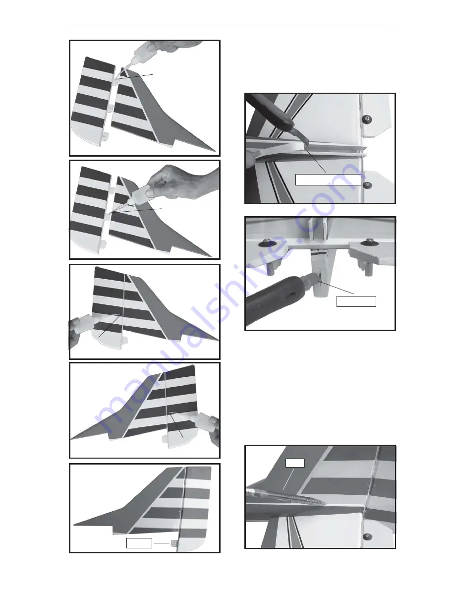
1)  Using a modeling knife, remove the

covering from the top of the fuselage and the
covering from over the precut hinge slot cut
into the lower rear portion of the fuselage This
slot accepts the lower vertical.

C/A glue.

C/A glue.

C/A glue.

C/A glue.

Hinge.

Pen.

2) Slide the vertical stabilizer into the slot

in the top of the fuselage. The bottom edge of
the stabilizer should also be firmly pushed
against the top of the horizontal stabilizer.

3) While holding the vertical stabilizer

firmly in place, use a pen and draw a line on
each side of the vertical stabilizer where it
meets the top of the fuselage.

Remove covering.

Hinge slot.

Summary of Contents for SPEED AIR-40

Page 1: ...SPECIFICATION Wingspan 1 500 mm 59 in Length 1 160 mm 46 in Weight 2 4 kg 5 28 Lbs Radio 04 channels Servo 05 servos Engine 40 46 2 stroke 52 4 stroke Instruction Manual book Made in Vietnam...

Page 2: ...ock Paper towels Some more parts HARDWAREPACK COWLING Landing gear To avoid scratching your new airplane do not unwrap the pieces until they are needed for assembly Cover your workbench with an old to...

Page 3: ...if people are near Do not stand in line with the side of the propeller Make engine adjustments from behind the propeller only Do not reach around the spinning propeller SAFETY PRECAUTION SERVO INSTALL...

Page 4: ...ng 3 Drill 1 5mm pilot holes through the block of wood for each of the four mounting screws provided with the servo Install servo into ai leron servo tray as same as picture below 4 Using the thread a...

Page 5: ...on control Control horn of Aileron 1 Using a ruler pen to draw a straight line as below picture 2 Locate nylon control horn nylon con trol horn backplates Mark line 3 Drill through 6mm diameter the ai...

Page 6: ...aluminium wing dihedral brace INSTALLING THE AILERON LINKAGES Repeat the procedure for the other wing half Installing the aileron linkages as pictures below Attach the clevis to the outer hole in the...

Page 7: ...brace should slide in easily If not use 220 grit sandpaper with a sanding block and sand down the edges and ends of the brace until it fits properly Aluminium brace A B Epoxy PLUS A B glue A B glue A...

Page 8: ...the rear of the tank and move freely inside the tank Connect one end of the line to the weighted clunk and the other end to the nylon pick up tube in the stop per FUEL TANK 3 Carefully bend the secon...

Page 9: ...ine 150mm long Connect 2 lines to the 2 vent tubes and 1 line to the fuel pickup tube in the stopper Blow through one of the lines to ensure the fuel lines have not become kinked inside the fuel tank...

Page 10: ...SPEED AIR 40 Instruction Manual 10 Steering arm Adjust the nose gear steering arm until the arm is parallel with the fire wall Installing steering arm as follow Steering arm NOSE GEAR INSTALLATION...

Page 11: ...his Z bend should be inserted into the throttle arm of the engine when the engine is fitted onto the engine mount Fit the engine to the engine mount using the screws provided INSTALLING THE ENGINE Pus...

Page 12: ...fuselage for the stabilizer and remove it 2 Mount the servo to the tray using the mounting screws provided with your radio sys tem 1 Install the rubber grommets and brass collets into the elevator se...

Page 13: ...al stabilizerthe into the fuselage 4 Remove the stabilizer Using the lines you just drew as a guide carefully remove the covering from between them using a model ing knife 3 With the stabilizer held f...

Page 14: ...emove the masking tape or T pins used to hold the stabilizer in place Carefully inspect the glue joints Use more epoxy to fill in any gaps that may exist that were not filled previously and clean up t...

Page 15: ...SPEED AIR 40 Instruction Manual 15 C A glue C A glue Bottom 2 Install control horn as same as picture below Remove covering...

Page 16: ...SPEED AIR 40 Instruction Manual 16 Cut Elevator servo VERTICAL STABILIZER INSTALLATION Bend Secure Hinge...

Page 17: ...ower vertical C A glue C A glue C A glue C A glue Hinge Pen 2 Slide the vertical stabilizer into the slot in the top of the fuselage The bottom edge of the stabilizer should also be firmly pushed agai...

Page 18: ...slot in the mounting platform and to the vertical stabilizer mounting area Apply epoxy to the lower rudder hinge Set the stabilizer in place and re align Double check all of your measurements once mo...

Page 19: ...the protective foam to protect them from vibration INSTALLING THE RECEIVERAND BATTERY Battery 3 Do not permanently secure the receiver and battery until after balancing the model 4 Using a 2mm drill...

Page 20: ...Manual 20 Cut Thottl pushrod Switch 2 Secure the switch in place using the two machine screws provided with the radio system Secure Secure servo tray on to the fuselage ATTACHMENT WING FUSELAGE See p...

Page 21: ...correctly Improper balance will cause your plane to lose control and crash THE CENTER OF GRAVITY IS LOCATED 95mm BACK FROM THE LEADING EDGE OF THE WING BALANCING 2 Turn the airplane upside down Place...

Page 22: ...Rudder 15mm right 15mm left 1 Completely charge your transmitter and receiver batteries before your first day of flying 2 Check every bolt and every glue joint in your plane to ensure that everything...

Reviews: