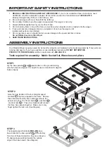


STEP 8
Assemble the front and rear panels
using the 80mm pins and clips .
Again, the flat side of each panel should be
on the outside.
STEP 9
Before engaging the locking
mechanism to lock the side panels into
place with the front and rear panel,
assemble the four connector brackets to the
base panels using the sixteen 10 x 20mm bolts ,
washers , and lock nuts . Use a
screwdriver if necessary to align holes properly.
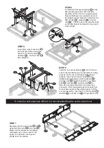
STEP 10
Attach the side panel brackets to the base
panels using the two 8 x 20mm bolts ,
washers , and lock nuts . The circular tube
for the pin should face inward. Insert one 100mm
pin and clip in each side to secure the
brackets to the side panels.
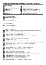
STEP 12
Prior to attaching the wheels and the
handle, firmly tighten all bolts and lock
nuts from prior steps.
STEP 13
Slide the four wheels onto each
axle. Place a 20mm washer on
the outside of each tire and slide a large
cotter pin into the hole in the axle.
Be sure to bend one side of the cotter
pin for a secure attachment.
STEP 14
Install the tractor pull handle into the
front part of the yoke using the
12 x 60mm bolt , washer , and
lock nut . The bolt should be tight, but
the handle should be able to move up and
down freely.
STEP 11
Test the locking mechanism on the front and rear panels. To make any
adjustments, tighten or loosen the nuts on the locking mechanism.
Lock all panels into place.
To make the next steps less difficult, it is again recommended that the unit be turned over.
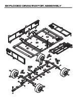
Connector
Brackets
Connector
Brackets
Side Panel
Bracket
3
4
4
29
29
31
3
31
26
15
6
22
5
25
18
23
31
30
6
5
30
31
15
26
22
18
25
23
10
10
10
10
10
28
28
35
33
14
20
27
24
20
27
24
14