background image















15













®

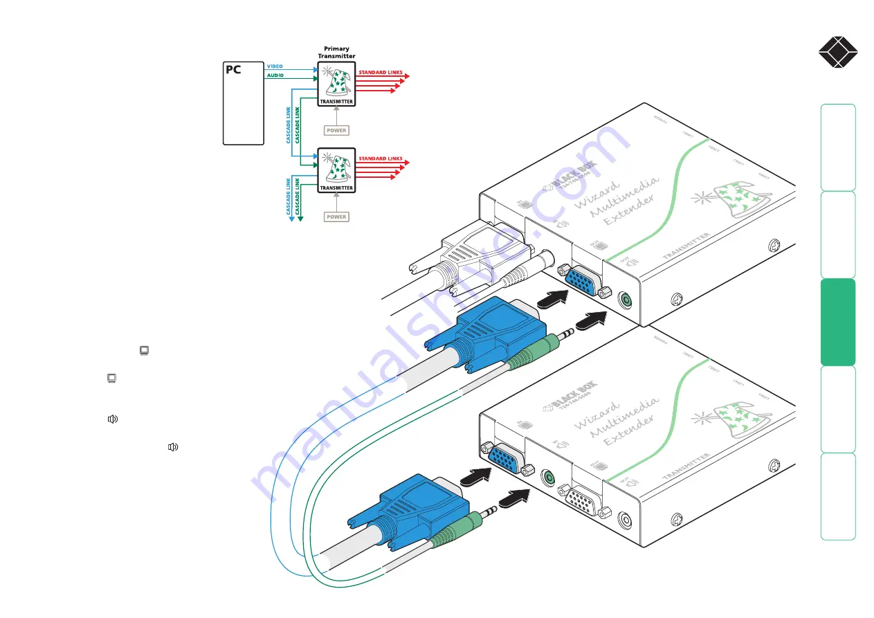
Cascading transmitters

Expansion at the transmitter end 
is achieved using the video and 
audio output ports. The signals 
from these ports are connected to 
the video and audio inputs of the 
next transmitter and so on. Wizard 
AVU5001A and AVU5004A 
transmitters can be mixed in a 
cascade in any order using the 
method discussed here. 

NOTE: Ensure that there are no more than 
three cascades (transmitter or receiver cascades) 
between the primary transmitter and the furthest 
receiver in any branch.

To connect cascaded transmitters

1  Attach a video cable of suitable type and length (fully shielded with 

15 way male D-type connectors at both ends, 6 feet or less) to the 
socket labelled 

OUT

 on the primary Wizard transmitter.

2  Attach the other end of the video cable to the socket 

labelled 

IN

 on the secondary Wizard transmitter.

3  Attach a stereo audio cable (shielded with three way 

3.5mm jack plugs at both ends) to the socket 
labelled 

OUT

 on the primary Wizard transmitter.

4  Attach the other end of the stereo audio cable 

to the socket labelled 

IN

 on the secondary 

Wizard transmitter.

5  Repeat such cascade links until the 

required number of transmitters (up to a 
maximum of four) are present. Connect 
the remaining signal and power cables 
to the added transmitters (and their 
respective receivers) as discussed earlier 
within this chapter. 

Primary transmitter

Secondary transmitter

Summary of Contents for Wizard AVU5001A

Page 1: ...l 724 746 5500 FREE technical support 24 hours a day 7 days a week Call 724 746 5500 or fax 724 746 0746 Mailing address Black Box Corporation 1000 Park Drive Lawrence PA 15055 1018 Web site www blackbox com E mail info blackbox com CUSTOMER SUPPORT INFORMATION MARCH 2006 AVU5001A AVU5004A AVU5010A AVU5011A AVU5111A ...

Page 2: ...he transmitter 9 Connections at the receiver 12 Making cascade connections 14 Important limitations when cascading 14 Cascade connection examples 14 Cascading transmitters 15 Cascading receivers Wizard AVU5111A only 16 Operation Indicators 17 Adjustments 17 Brightness and sharpness adjustments 17 Skew compensation adjustments AVU5111A only 18 Further information Troubleshooting 20 Getting assistan...

Page 3: ...her similar transmitters to the original module each supporting their own receiver modules The standard transmitter and receiver modules are also available separately and are known as the AVU5001A transmitter and AVU5011A receiver respectively Wizard AVU5004A and AVU5111A The Wizard AVU5004A transmitter and multiple AVU5111A modules are designed to provide potentially enormous expansion possibilit...

Page 4: ...eceiver can then drive its own dual display speaker sets as well as provide a further LINK OUT to a third and final AVU5111A receiver A limit of three cascade connections comprising both transmitter and or receiver cascades is possible within any branch of the system Either of the Wizard AVU transmitters can be connected in cascade to provide further audio and video expansion opportunities The Wiz...

Page 5: ...AVU5011A are packaged as a transmitter and receiver pair AVU5010A as well as being available separately The Wizard AVU5004A and AVU5111A modules are only available separately Stereo audio cable to connect a transmitter to the source PC and optionally to connect additional transmitter modules in cascade CD ROM containing skew test pattern and documentation For part numbers of other items please als...

Page 6: ...odule AVU5111A model pictured Power supply connection Link output to cascaded receiver AVU5111A only Indicators Link input from transmitter or cascade input Audio output to speakers Video output to display Audio output to speakers Video output to display Variation for AVU5001A transmitter Single link out connector Brightness control Sharpness control Skew adjusters not AVU5011A Variation for AVU50...

Page 7: ...smitters are as close as possible to the source PC system and the receivers are similarly close to the display modules Use video connection cables that are correctly shielded and are no longer than 6m in length Wherever possible choose routes for the CATx twisted pair link cables that avoid mains power cables Remember a mains power socket is required for each transmitter and receiver Consult the p...

Page 8: ... the internal circuitry 5mm 0 19 9 5mm 0 37 Using the self adhesive feet Apply the supplied self adhesive rubber feet to the underside corners of the Wizard modules Mounting Before you begin connecting to the source PC system and display devices it is advisable to mount the Wizard modules in place There are a number of mounting possibilities for the transmitter and receiver modules On a horizontal...

Page 9: ...away from the rack 3 Slide the module into the required rack position 4 The rack mount chassis has a series of holes in its floor that are spaced to accommodate the screws on the module s lower edge Ensure that the screws correctly locate into the holes of the chosen slot The rack securing plate on the module should now be flush with the front of the rack mount chassis 5 Use the supplied pan head ...

Page 10: ...eo cable to the appropriate VGA video output socket on the source PC system 3 Attach a stereo audio cable shielded with three way 3 5mm jack plugs at both ends to the socket labelled IN on the Wizard transmitter 4 Attach the other end of the stereo audio cable to the appropriate audio output socket on the source PC system To connect a monitor and speakers The video and audio out ports of the Wizar...

Page 11: ...ace 2 Attach the connectors of the remaining link cables to the sockets labelled LINK2 to LINK4 as required In all cases there should be a click when the cable is fully inserted and locked in place However if further receivers are connected in cascade to the initial receiver using its LINK OUT port Wizard AVU5111A models only then the overall length of the link cables used must be reduced For furt...

Page 12: ...hed power socket or extension cord 1 Attach the output connector of the power supply to the socket labelled POWER on the Wizard transmitter 2 Insert the IEC connector of the power cord into the corresponding socket of the power supply 3 When all other connections have been made at the transmitter and receiver modules connect the other end of the power cord to a nearby earthed mains socket ...

Page 13: ...ascade connections NOTE Where possible avoid laying the twisted pair link cable s alongside power cables 1 Attach the connector of the link cable to the socket labelled LINK IN on the Wizard receiver There should be a click when the cable is fully inserted and locked in place Connections at the receiver To connect displays and speakers Dual video and audio outputs are provided on the Wizard receiv...

Page 14: ...thed power socket or extension cord 1 Attach the output connector of the power supply to the socket labelled POWER on the Wizard receiver 2 Insert the IEC connector of the power cord into the corresponding socket of the power supply 3 When all other connections have been made at the transmitter and receiver modules connect the other end of the power cord to a nearby earthed mains socket ...

Page 15: ...ink length for a branch count the number of cascade connections between the primary transmitter and the final receiver in that branch The effects of cascade connections on overall branch link lengths are as follows Number of cascade connections Overall length of links for a branch in a branch from transmitter to furthest receiver 0 300m 1000 feet 1 250m 800 feet 2 200m 650 feet 3 175m 600 feet Not...

Page 16: ...hielded with 15 way male D type connectors at both ends 6 feet or less to the socket labelled OUT on the primary Wizard transmitter 2 Attach the other end of the video cable to the socket labelled IN on the secondary Wizard transmitter 3 Attach a stereo audio cable shielded with three way 3 5mm jack plugs at both ends to the socket labelled OUT on the primary Wizard transmitter 4 Attach the other ...

Page 17: ... receivers Each Wizard AVU5111A receiver provides two extra adjustment dials to counter skew effects For further information please refer to the section Skew compensation adjustments To connect cascaded receivers NOTE Please observe the recommended overall link cable lengths including receiver cascade connections in order to avoid signal degradation 1 Attach the connector of the cascade link cable...

Page 18: ...dges such as black lines on a white background NOTE Both video outputs are equally affected by your brightness and or sharpness adjustments To display a suitable high contrast image Open a word processor type the capital letter H or M and increase the point size to 72 or higher For best results the background should be white and the character should be black A BLACK shadow on the right of the char...

Page 19: ...n as discussed opposite NOTE Both video outputs are equally affected by your skew adjustments SKEW RG dial SKEW GB dial To create a skew test pattern 1 Run any image creation editing application such as the Paint program supplied with Windows 2 Using the image application create three stacked horizontal rectangles one red one green and one blue that fill the width of the screen 3 Draw a vertical b...

Page 20: ...uccessful skew compensation adjustment will be improved if you do the following Ensure that you have a clear view of one or both display screens Display a suitable RGB test pattern either the supplied pattern or a self created version Use a screwdriver of an appropriate size to adjust the dials Begin with both skew dials in their neutral positions if the module has been previously used and skew ad...

Page 21: ...e at the receiver module is distorted or shadows appear to the right of displayed objects Adjustments are required to compensate for the length of the twisted pair cable being used If video problems persist Please refer to the Brightness and sharpness adjustments section in the Operation chapter If the overall video image is fuzzy and or has colored shadows you may need to make skew adjustments Wi...

Page 22: ...upplies can get warm in operation do not situate them in an enclosed space without any ventilation The modules do not provide ground isolation and should not be used for any applications that require ground isolation or galvanic isolation Use only with grounded outlets at both the computer and monitor When using a backup power supply UPS power the computer the monitor and the module from the same ...

Page 23: ...he equipment and the receiver c Connect the equipment to an outlet on a circuit different from that to which the receiver is connected d Consult the supplier or an experienced radio TV technician for help FCC Compliance Statement United States This equipment generates uses and can radiate radio frequency energy and if not installed and used properly that is in strict accordance with the manufactur...

Page 24: ...por los orificios de ventilación 10 El equipo eléctrico deber ser situado fuera del alcance de fuentes de calor como radiadores registros de calor estufas u otros aparatos incluyendo amplificadores que producen calor 11 El aparato eléctrico deberá ser connectado a una fuente de poder sólo del tipo descrito en el instructivo de operación o como se indique en el aparato 12 Precaución debe ser tomada...

Page 25: ... ctxd com Documentation by 2006 Black Box Corporation All trademarks are acknowledged Black Box Corporation 1000 Park Drive Lawrence PA 15055 1018 United States of America Tel 1 724 746 5500 Fax 1 724 746 0746 ...

Page 26: ... 606 747 tech blackbox fr Germany www black box de 49 811 5541 110 49 811 5541 499 techsupp black box de Italy www blackbox it 39 02 27 404 700 39 02 27 400 219 supporto tecnico blackbox it Netherlands www blackbox nl 31 30 241 7799 31 30 241 4746 techsupport blackbox nl Norway www blackboxnorge no 47 55 300 710 47 55 300 701 support blackboxnorge no Spain www blackbox es 34 9162590732 34 91623978...

Reviews: