background image

9

CHAPTER 2: Overview

2.2 Components

2.2.1 F

RONT

P

ANEL

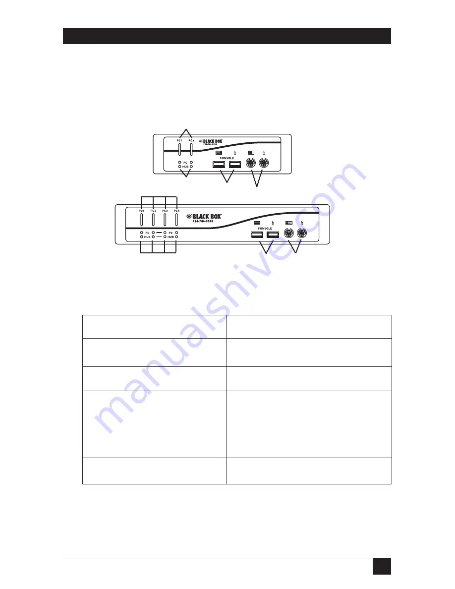
Figure 2-1 shows the 2- and 4-Port ServSwitch front views. Table 2-1 describes the
components numbered in the illustration.

Figure 2-1. The ServSwitch front-panel views.

Table 2-1. Front-panel components.

Component

Description

6-pin mini-DIN connectors

PS/2 keyboard and mouse ports.

Direct-access port buttons

Press to select a computer.

Port LEDs and Hub LEDs

Port LEDs located below the port

buttons light when the connected

computer is selected. Hub LEDs light to

indicate which port has the hub control.

USB ports

USB keyboard and mouse ports.

Summary of Contents for ServSwitch DT Pro II KV7020A

Page 1: ...24 746 5500 FREE technical support 24 hours a day 7 days a week Call 724 746 5500 or fax 724 746 0746 Mailing address Black Box Corporation 1000 Park Drive Lawrence PA 15055 1018 Web site www blackbox...

Page 2: ...couraged to try to correct the interference by one of the following measures Reorient or relocate the receiving antenna Increase the separation between the equipment and receiver Connect the equipment...

Page 3: ...7 El aparato el ctrico debe ser montado a la pared o al techo s lo como sea recomendado por el fabricante 8 Servicio El usuario no debe intentar dar servicio al equipo el ctrico m s all a lo descrito...

Page 4: ...r una antena externa deber ser localizada lejos de las lineas de energia 16 El cable de corriente deber ser desconectado del cuando el equipo no sea usado por un largo periodo de tiempo 17 Cuidado deb...

Page 5: ...Inc PS 2 is a registered trademark of International Business Machines Corporation Linux is a registered trademark of Linus Torvalds IntelliMouse Microsoft Windows and Windows NT are either registered...

Page 6: ...tch Placement 12 3 2 Hardware Installation 12 3 2 1 Connecting the Console 12 3 2 2 Powering On the ServSwitch 14 3 2 3 Connecting the Computers 15 3 2 4 Connecting the USB Peripherals 16 4 Operation...

Page 7: ...Type A female Monitor 1 HD15 female USB peripherals 2 USB Type A female Microphone speaker 2 3 5 mm jacks Power 1 barrel connector KV7021A Computer end PS 2 keyboard PS 2 mouse and VGA video 4 HD15 f...

Page 8: ...CHAPTER 1 Specifications Power 9 VDC power supply Size KV7020A 1 8 H x 5 4 W x 3 5 D 4 5 x 13 8 x 9 1 cm KV7021A 1 8 H x 8 7 W x 4 1 D 4 5 x 22 x 10 5 cm Weight KV7020A 1 8 lb 0 8 kg KV7021A 2 lb 0 9...

Page 9: ...y switch the KVM control and the USB devices And the ServSwitch works with common operating systems including Windows 98 Me 2000 XP Windows NT Linux Novell NetWare and Mac OS Setup is fast and simple...

Page 10: ...witch front panel views Table 2 1 Front panel components Component Description 6 pin mini DIN connectors PS 2 keyboard and mouse ports Direct access port buttons Press to select a computer Port LEDs a...

Page 11: ...sole VGA port Attaches to the user monitor Computer VGA ports Connect to a computer s video cards and keyboard and mouse when used with PS 2 computers Computer USB 1 1 Link to a computer s USB 1 1 key...

Page 12: ...h 1 Power supply for U S Europe Great Britain and Australia This user s manual 2 4 What You ll Need to Supply ServSwitch DT Pro II Cable EHN7002021 0006 0009 0015 These cables connect to PCs that have...

Page 13: ...conditioning equipment etc 3 2 Hardware Installation This section provides instructions for the basic hardware setup of a single ServSwitch CAUTION Before you begin make sure that power to all the dev...

Page 14: ...console VGA port on the back of the ServSwitch See Figure 3 2 Figure 3 2 Console connections 4 Connect the speaker and microphone connectors from your computer to the audio ports on the back of the u...

Page 15: ...ions 3 2 2 POWERING ON THE SERVSWITCH Connect the 9 VDC power adapter s barrel connector to the power jack on the rear of the switch Then plug the power adapter cable into an available power outlet Se...

Page 16: ...corresponding connectors on the back of the computer Figure 3 5 USB computer connections 3 Repeat steps 1 and 2 for all computers 4 Power on your computers Your computers operating systems should reco...

Page 17: ...IPHERALS Attach up to two USB peripherals to the USB Type A connectors on the ServSwitch See Figure 3 6 NOTE You can attach a USB keyboard and mouse but hotkey switching will not be enabled for these...

Page 18: ...he port selector buttons on the front panel The corresponding LED will light when the port is selected 4 3 Selecting Computers Using Keyboard Hotkey Commands To directly switch the KVM control to any...

Page 19: ...nnel number Left Ctrl Left Ctrl Fy Select audio microphone channel Select the active audio and microphone channel Joint select PC hub port control audio and microphone if binding is enabled Fy F5 F6 o...

Page 20: ...ow Next lower PC channel Select the next lower PC channel Joint select PC hub port control audio and microphone if binding is enabled Left Ctrl Left Ctrl down arrow Next higher PC channel Select the n...

Page 21: ...utoscan with a user defined delay time within a range of 10 to 100 seconds z 0 9 for 10 20 30 40 50 60 70 80 90 or 100 seconds Press any key on keyboard Stop Autoscan Left Ctrl Left Ctrl V Show the cu...

Page 22: ...ing the nature and duration of the problem when the problem occurs the components involved in the problem any particular application that when used appears to create the problem or make it worse A 2 S...

Page 23: ...1000 Park Drive Lawrence PA 15055 1018 724 746 5500 Fax 724 746 0746 Copyright 2007 Black Box Corporation All rights reserved...

Reviews: