


3.3.
CONNECTING RAS-PUTIN TO THE HOST SYSTEM
13
Hint:
IPMI V1.5 is only supported by modern server systems. No server system manufactured
before 2002 supports IPMI 1.5. By the date of printing this manual only the Intel SDS2
server main board has a proper support of IPMI Verson 1.5.
Connect the IPMI option serial cable to the RS232 port 1 on the rear side of RAS-PutIn and
to the serial port of the controlled system.
3.3.3 Connecting the Internal Reset/Power Option
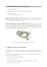
Figure
shows the top view of the reset/power bracket.
To Reset Pin on
Mainboard
To Reset Front
Panel switch
To Power on Pin on
Mainboard
To Power Front
Panel switch
Figure 3.8: Top view of internal reset/power option
Additional cables are required in order to enable the remote reset and the remote power function
of RAS-PutIn:
1. Mount the reset/power bracket in a free slot of the controlled system.
2. Find the cable connecting the front panel reset button and the main board.
3. Disconnect this cable from the main board and connect it to the pin connector on the
bracket as shown in Figure
4. Take the supplied red/black reset cable and connect the cable with one end to the main
boards reset jumper connector (where you just disconnected the cable to the front panel)
and with the other end to the bracket connector as shown in Figure
5. Find the cable connecting the front panel power button and the main board.
6. Disconnect this cable from the main board and connect it to the pin connector on the
bracket as shown in Figure
7. Take the supplied red/black power cable and connect the cable with one end to the main
board’s power jumper connector (where you just disconnected the cable to the front panel)
and with the other end to the bracket connector as shown in Figure
8. Check the cabling: finally, there are four cables connected to the jumper connector on the
bracket.
Now, connect the bracket to the RAS-PutIn serial port 2 using the supplied SUB-D 9 to SUB-D
9 connector.
3.3.4 Connecting the External Reset/Power Option
Please refer to the manual of the Blackbox external power switch option or a third party external
power option to connect those external devices to one of the serial interface on the rear side of
Summary of Contents for RAS-PutIn
Page 1: ...RAS PutIn Installation and User Guide Based on Firmware 03 02 07 ...
Page 4: ...iv ...
Page 8: ...viii Contents ...
Page 12: ...xii List of Tables ...
Page 30: ...18 CHAPTER 4 CONFIGURATION ...
Page 76: ...64 CHAPTER 5 USAGE ...
Page 80: ...68 APPENDIX A GLOSSARY ...
Page 82: ...70 APPENDIX B RAS PUTIN VIDEO MODES ...
Page 88: ...76 APPENDIX D PIN ASSIGNMENTS ...
Page 92: ...80 APPENDIX F SPECIFICATIONS ...


