


12
1.877.877.2269
BLACKBOX.COM
NEED HELP?
LEAVE THE TECH TO US
LIVE 24/7
TECHNICAL
SUPPORT
1.877.877.2269
CHAPTER 3: INSTALLATION
STEP 3: CONNECT CABLES
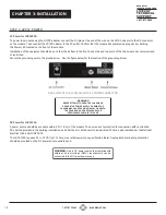
a. Insert the SFP transceiver into the SFP receptacle on the front of the module.
NOTE: The release latch of the SFP Fiber transceiver must be in the closed (up) position before insertion.
b. Connect an appropriate multimode or singlemode fiber cable to the SFP on the front of the module. It is important to ensure
that the transmit (TX) is attached to the receive side of the module at the other end and the receive (RX) is attached to the transmit
side. When using a single-fiber (SF) SFP, the TX wavelength must match the RX wavelength at the other end and the RX wavelength
must match the TX wavelength at the other end.
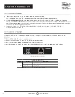
c. Connect the Ethernet 10/100/1000 RJ-45 port via a Category 5 or better cable to an external 10BASE-T, 100BASE-TX,
or 1000BASE-T Ethernet PD device.
STEP 4: VERIFY OPERATION
Once the module has been installed and configured per steps 1 through 4, verify the module is operational by viewing the LED
indicators.
The Power LED indicates the module is receiving power.
The Fiber Optic LEDs indicates the fiber optic connection has been established.
The RJ-45 10/100/1000 LEDs indicate the speed of the RJ-45 port connection.
The PSE LED indicates the module has established a successful detection of a PD and is supplying Power over Ethernet.
LED INDICATOR LOCATIONS
POWER LED INDICATORS
Legend
Indicator
Description
Pwr
OFF
Unit not powered
Green - ON
Unit powered
Amber - ON
Over temperature condition


