background image


Express Ethernet Switch: LB9017A-R3 

User’s Manual 

17 

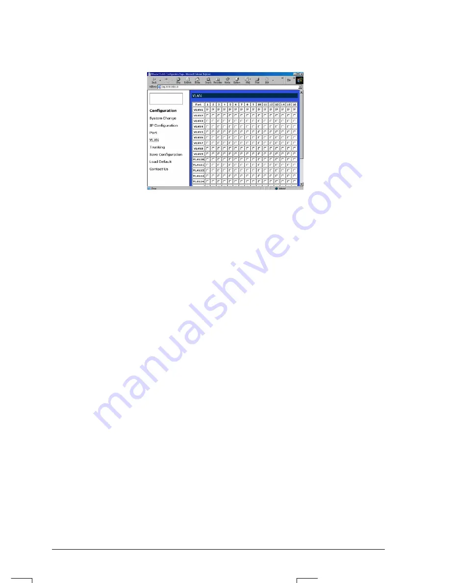
VLAN 


z


VLAN: Click and choose the ports to be added into the VLAN groups. 

z


Apply: Click the 

Apply 

button and apply the new settings of the VLAN groups. 

<Note> All Ports have to be selected to one of the VLAN Groups, those Port/Ports were not 
selected will be notified by the alarm message which shows “ Non-Identify VLAN Group 
On Port “. 


Summary of Contents for LB9017A-R3

Page 1: ...toll free in the U S 24 hours 7 A M Monday to midnight Friday 877 877 BBOX FREE technical support 24 hours a day 7 days a week Call 724 746 5500 or fax 724 746 0746 Mail order Black Box Corporation 10...

Page 2: ...idad y operaci n deber n ser guardadas para referencia futura 3 Todas las advertencias en el aparato el ctrico y en sus instrucciones de operaci n deben ser respetadas 4 Todas las instrucciones de ope...

Page 3: ...do de tal manera que objectos liquidos no sean derramados sobre la cubierta u orificios de ventilaci n 18 Servicio por personal calificado deber ser provisto cuando A El cable de poder o el contacto h...

Page 4: ...tional 100BaseFX multi mode or single mode fiber module enabling long distance connection To get the most out of this manual you should have an understanding of networking concepts such as bridging IE...

Page 5: ...iber Module Installation 10 Figure 4 Removal of cover plate Fiber module being installed 10 Connecting to Power 11 Figure 5 Rear view of the switch 11 Connecting to Your Network 11 Cabling 11 Network...

Page 6: ...d Smart Ethernet Switch Package Contents When you unpack the product package you shall find these items listed below 3 The 16 Ports Switch 3 One AC power cord 3 User s Manual Please inspect the conten...

Page 7: ...ANISM TRUE NON BLOCKING ARCHITECTURE FULL WIRE SPEED FORWARDING RATE BROADCAST STORM FILTERING CONTROL BACK PRESSURE AND IEEE 802 3X COMPLIANT FLOW CONTROL SYSTEM IP CONFIGURATION PORT PORT BASED VLAN...

Page 8: ...s The RJ 45 ports are numbered from 1 to 16 on the 16 Port Switch The LEDs are located on the ports of the switch displaying status for each respective port Please refer to the table below for more in...

Page 9: ...allation Selecting a Site for the Equipment As with any electric device you should place the equipment where it will not be subjected to extreme temperatures humidity or electromagnetic interference S...

Page 10: ...tep 3 Carefully position the switch into the rack Step 4 Align the brackets to the side holes on the rack and use rack screws to secure the chassis with the rack Step 5 Proceed to the Connecting to Po...

Page 11: ...e static free container Step 3 Unscrew the cover plate of the expansion slot The slot for single port module is located at the right side of the switch Step 4 Remove the plate Keep it for future use i...

Page 12: ...to Your Network Cabling Step 1 First ensure the power of the switch and end devices is turned off LIt may cause an electric shock or any possible harm to you if the power is not switched off Step 2 Pr...

Page 13: ...ic cable is used Cable Specifications Table Ethernet Standards Connector Port Speed Half Ful l Duplex Cable Max Distanc e 10BaseT RJ 45 10 20 Mbps Cat 3 4 or 5 UTP STP 100 m 100BaseTX RJ 45 100 200 Mb...

Page 14: ...s directly in your web browser by entering the default IP address of the Ethernet Switch 192 168 1 10 You can then use your web browser to list and manage the Ethernet Switch configuration parameters...

Page 15: ...he System Change button in the left sub menu z Switch Name Type a switch name and replace the current switch name with a new one Please restart your Computer once the Switch Name is replaced and saved...

Page 16: ...ly can not exceed 16 characters z Apply Click the Apply button and apply the new System settings IP Configuration z Refresh Click the Refresh button and refresh back to the last saved IP Configuration...

Page 17: ...while you change the settings of the ports The Refresh On will refresh the settings of the ports shown on the screen around every ten seconds z Mode Choose AUTO 10HD 10FD 100HD or 100FD for the ports...

Page 18: ...s to be added into the VLAN groups z Apply Click the Apply button and apply the new settings of the VLAN groups Note All Ports have to be selected to one of the VLAN Groups those Port Ports were not s...

Page 19: ...Disable to disable the Trunking Group 1 or Trunking Group 2 z Trunking Group 1 Click and choose the Port 1 2 to be added into the Trunking Group 1 z Trunking Group 2 Click and choose the Port 9 10 to...

Page 20: ...z Click Save Configuration z Click the Ok or Cancel button to or not to save the configurations Note The Cancel button will discard any data you have changed since the last Save operation Without cli...

Page 21: ...h Applicable Standards IEEE 802 3 10BaseT IEEE 802 3u 100BaseTX FX Fixed Ports Sixteen ports for the 16 Port Switch Optional 1 port Module Type 100BaseFX multi mode or single mode module 100BaseTX FX...

Page 22: ...8 2 x 1 74 in W440 D207 H44 mm 19 rack mount size 1U high Weight Approximately 6 2 pounds 2 8kg Power Input 100 240 VAC 50 60 Hz Input Fuse 16 Ports 3 3Volts DC 4A Power 16 Ports 15W Maximum Operatin...

Page 23: ...tor and Cable Pins The following table lists the pinout of 10 100BaseT TX ports Connector Pin Out Pin Regular Ports Uplink port 1 Input Receive Data Output Transmit Data 2 Input Receive Data Output Tr...

Page 24: ...F 50 m or 62 5 m MT RJ 2km 100BaseFX MMF 50 m or 62 5 m VF 45 2km 100BaseFX MMF 50 m or 62 5 m LC 2km 100BaseFX SMF 9 m or 10 m SC 15km 100BaseFX SMF 9 m or 10 m SC 40km 100BaseTX Cat 5 or better UTP...

Reviews: