background image

724-746-5500   |   blackbox.com 

Page 26

KVT517A-R2

Chapter 4: Operation

4.3.3 Opening the Keyboard/Touch Pad and LCD Monitor Individually

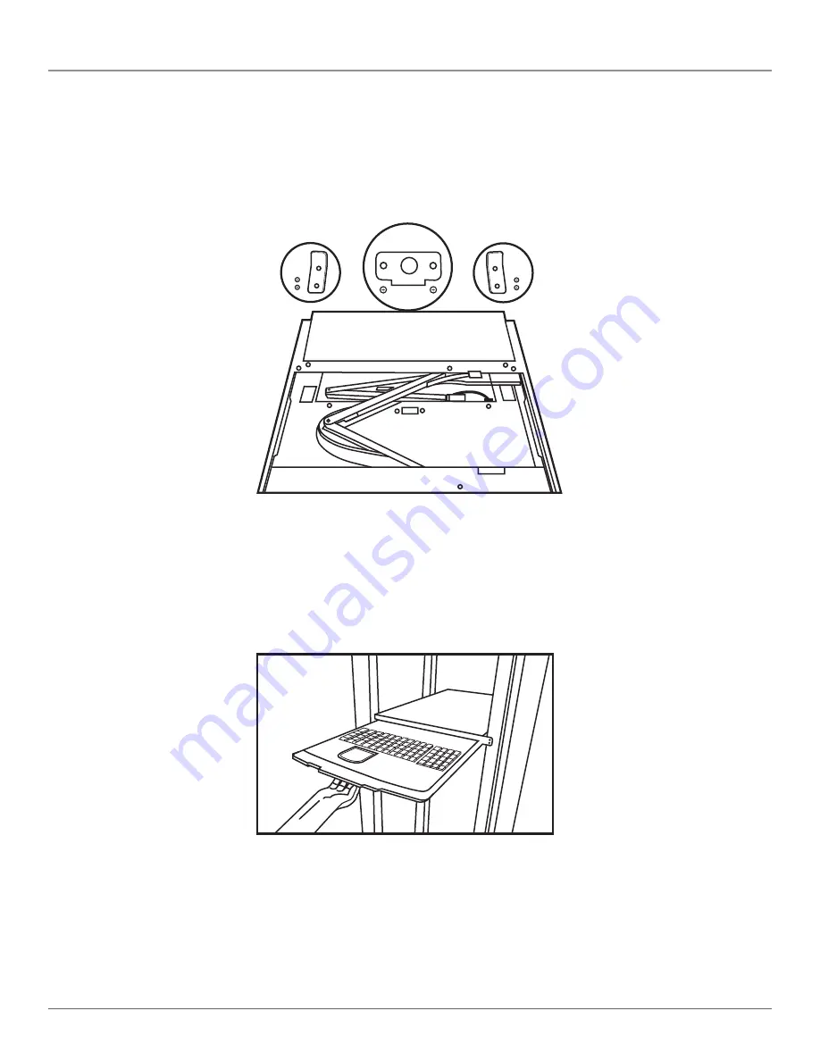
1.  To pull out the keyboard touch pad independently, you must first remove the two pairs of screws fastened on a bracket at the 

keyboard’s upper cover on the ends of the left and right sides. See Figure 4-9.

(2) screws  

and brackets

(2) screws  

and brackets

Figure 4-9. Screws on the keyboard/touch pad and LCD monitor assembly.

2. Unscrew and remove the screws one at a time. 

3.  Then put the screws aside and pull out the keyboard/touch pad and LCD monitor individually. See Figure 4-10.

Figure 4-10. Pulling out the keyboard/touch pad and LCD monitor.

Summary of Contents for KVT517A-R2

Page 1: ...ew V KVM tray Widescreen model is now available ServView V KVM Tray KVT517A R2 KVT517A WIDE R3 Order toll free in the U S Call 877 877 BBOX outside U S call 724 746 5500 FREE technical support 24 hour...

Page 2: ...xperts in less than 60 seconds Trademarks Used in This Manual Black Box and the Double Diamond logo are registered trademarks and ServView and ServSwitch are trademarks of BB Technologies Inc Centroni...

Page 3: ...ce when the equipment is operated in a commercial environment Operation of this equipment in a residential area is likely to cause interference in which case the user at his own expense will be requir...

Page 4: ...mpidan el flujo de aire por los orificios de ventilaci n 10 El equipo el ctrico deber ser situado fuera del alcance de fuentes de calor como radiadores registros de calor estufas u otros aparatos incl...

Page 5: ...ration 20 4 1 KVM Control and Status LEDs 20 4 2 Extra Keyboard and Mouse Control 22 4 3 Opening and Closing the Console 23 4 3 1 Opening the Console 23 4 3 2 Closing the Console 25 4 3 3 Opening the...

Page 6: ...1280 x 1024 60 70 75 Hz 1920 x 1080P VGA Resolution for Optimum Performance 1280 x 1024 60 Hz 1920 x 1080P Viewing Angle Typical 80 to 80 H 80 to 80 Horizontal Right Min 70 Typical 80 degrees CR 10 L...

Page 7: ...ximum resolution of 1920 x 1080P Install the ServView in 4 post racks or cabinets that have rail space of 23 7 D to 45 3 D 60 2 to 115 1 cm NOTE This is the depth measured between the front pole and r...

Page 8: ...a ServView V KVM Tray a PS 2 or USB KVM module and a universal rear bracket extension kit Table 2 1 lists the available kits Table 2 1 ServView V KVM Tray Kit components Kit Part Number KVM Module P N...

Page 9: ...2 or USB VGA KVT4S16PV 16 port PS 2 VGA KVT4S16UV 16 port PS 2 or USB VGA KVT517A 8DV WIDE R3 8 port USB DVI KVT8CATUV 8 port CX CATx KVT16CATUV 16 port CX CATx KVT1IP8CATUV 8 port CX CATx with 1 IP U...

Page 10: ...17A R2 Chapter 2 Overview 45 3 115 1 cm Figure 2 4 The maximum depth of the unit 23 7 60 2 cm Figure 2 5 The minimum depth of the unit Open rack post 1 Open rack post 2 ServView V Tray Figure 2 6 Serv...

Page 11: ...th your ServView V Kit to both sides of the KVM switch module See Figures 3 1 through 3 5 The wide edged plastic extension should be on the top side see Figure 3 5 NOTE The CATx KVM switch modules wil...

Page 12: ...A R2 Chapter 3 Assembly and Installation Extension Switch module Figure 3 3 Attaching the extensions to one side of the KVM switch module Extension on side of switch module Switch module Figure 3 4 KV...

Page 13: ...de Figure 3 5 Back view of module with extensions attached 3 Using four cabinet screws included screw the unit onto the rack See Figures 3 6 and 3 7 WARNING Do not remove the safety stopper until you...

Page 14: ...wheels with screws are inside the bracket s track while sliding in the rear bracket See Figure 3 7 ServView V KVM Tray Rear bracket Rear bracket Bracket track Figure 3 7 Install the rear bracket onto...

Page 15: ...the module See Figure 3 9 Screw Module Figure 3 9 Fasten the screw to the module 7 Remove the four screws held in place with safety stoppers from the front sides of the drawer left and right in sequen...

Page 16: ...stoppers Figure 3 11 Sliding the drawer out Figure 3 12 Removing the safety stoppers WARNING The safety stoppers prevent the drawer from sliding out when in transit Once you remove the safety stoppers...

Page 17: ...VM module 2 EVMPS03 0006 MM This side connects to the computer or server 2 6 pin mini DIN male VGA and USB HD15 female USB Type B male USB Type A male HD15 male This side connects to the KVM module Th...

Page 18: ...connects to a PS 2 console as shown in Figure 3 14 VGA USB VGA PS 2 DVI USB uses EVNPS06 0005 M F uses EVNPS06 0005 MF uses EHN900024U and USB01 0006 and 2 EVMPS03 0006 Figure 3 14 VGA USB VGA PS 2 an...

Page 19: ...ckbox com KVT517A R2 Chapter 3 Assembly and Installation VGA and USB VGA and PS 2 uses EHN9000U CPU cable uses EHN70001 CPU cable Figure 3 15 VGA and USB module HD15 OR 2 PS 2 connectors USB Type A ma...

Page 20: ...CATUV KVT1IP8CATUV KVT1IP16CATUV KVT4IP16CATUV is installed in the ServView V Tray It does not apply to the 1 port KVM switch module KVT6S1UV R2 CAB Figures 4 1 and 4 2 show the ServView V Tray s LCD...

Page 21: ...rts A H are selected the indicator lights flash red 3 LCD power button Press this button to turn on power When power is on the LCD lights 4 Auto key Press this dual function button to automatically ad...

Page 22: ...mouse Push and lift the lid as shown in Figure 4 3 Via a slide switch choose wireless keyboard and mouse combination or wireless mouse only for a keyboard mouse transceiver Touch pad function disabled...

Page 23: ...is pulled out This may cause personal injury and or property damage Do not put your fingers hands or anything else on the rear cabinet Do not touch any part behind the rear cabinet Keep the area behin...

Page 24: ...or screen display See Figure 4 6 Keyboard touch pad LCD monitor Figure 4 6 Lift out the LCD panel Opening LCD Monitor Only 1 Holding the LCD monitor s handle pull it upwards See Figure 4 7 Figure 4 7...

Page 25: ...sole back slowly and evenly See Figure 4 8 Metal plate Metal plate Figure 4 8 Closing the console CAUTION When the LCD monitor is pulled out all the way you will see both edges of two metal unlock pla...

Page 26: ...ned on a bracket at the keyboard s upper cover on the ends of the left and right sides See Figure 4 9 2 screws and brackets 2 screws and brackets Figure 4 9 Screws on the keyboard touch pad and LCD mo...

Page 27: ...1 Pull the keyboard out to the end and unfold the LCD monitor See Figure 4 11 Figure 4 11 Unfold monitor 2 There is a round hole under the drawer Using a finger push the keyboard up and through the h...

Page 28: ...rd inside the tray 3 Double check that the USB cable is placed inside the tray without any twist 4 Plug in the keyboard connector firmly See Figures 4 13 through 4 17 WARNING Make sure you place the U...

Page 29: ...Page 29 724 746 5500 blackbox com KVT517A R2 Chapter 4 Operation Figure 4 15 Correct way to replace the keyboard diagram 2 Figure 4 16 Wrong way to replace the keyboard diagram 2...

Page 30: ...OTE Make sure the triangular mark on the mini USB connector faces outwards 4 4 3 Alternate Way to Fasten the Keyboard Recommended 1 Pull the keyboard out as shown in Figure 4 5 2 Use the included six...

Page 31: ...imulates a wheel mouse When touching this area you will see two small triangular marks this is the simulated wheel See Figure 4 19 Touch pad Simulated wheel Figure 4 19 Touch pad showing simulated mou...

Page 32: ...ng the Touch Pad The touch pad attaches to the tray via a mini USB cable To replace the touch pad adjust the length of the mini USB cable and slide the touch pad all the way in until you hear a clicki...

Page 33: ...accurate assistance if you have a complete description including the nature and duration of the problem when the problem occurs the components involved in the problem any particular application that w...

Page 34: ...724 746 5500 blackbox com Page 34 KVT517A R2 NOTES...

Page 35: ...Page 35 724 746 5500 blackbox com KVT517A R2 NOTES...

Page 36: ...racks and power and surge protection products to media converters and Ethernet switches all supported by free live 24 7 Tech support available in 60 seconds or less Copyright 2015 Black Box Corporatio...

Page 37: ...teachers and staff Digital Signage for K 12 Everything you need to ask when planning and evaluating digital signage The Roadmap to Digital Signage Success Falling victim to these common mistakes can...

Page 38: ...standing the risks to your network and how to choose the right solution Power Protection Add low voltage devices and network equipment in industrial environments without running power Power over Ether...

Reviews: