background image

© Copyright 2000. Black Box Corporation. All rights reserved.

1000 Park Drive     ·     Lawrence, PA 15055-1018     ·     724-746-5500        Fax 724-746-0746

Summary of Contents for CityLIGHT LCL533A

Page 1: ...toll freeintheU S 24hours 7A M MondaytomidnightFriday 877 877 BBOX FREEtechnicalsupport 24hoursaday 7daysaweek Call 724 746 5500orfax724 746 0746 Mailorder BlackBoxCorporation 1000ParkDrive Lawrence PA15055 1018 Website http www blackbox com E mail info blackbox com CUSTOMER SUPPORT INFORMATION ...

Page 2: ...quipment is operated in a commercialenvironment Operationofthis equipment in a residentialarea is likely to causeinterference in which case the user at his own expense will be required to take whatevermeasuresmaybenecessarytocorrecttheinterference Changes or modifications not expressly approved by the party responsible for compliancecouldvoidtheuser sauthoritytooperatetheequipment Thisdigitalappar...

Page 3: ...co debe ser usado únicamente con carritos o pedestales que seanrecomendadosporelfabricante 7 El aparato eléctrico debe ser montado a la pared o al techo sólo como sea recomendadoporelfabricante 8 Servicio Elusuarionodebeintentardarservicioalequipoeléctricomásalláa lo descrito en las instrucciones de operación Todo otro servicio deberá ser referidoapersonaldeserviciocalificado 9 Elaparatoeléctricod...

Page 4: ...léctrico debe ser limpiado únicamente de acuerdo a las recomendacionesdelfabricante 15 Encasodeexistir unaantenaexternadeberá ser localizada lejos de las lineas deenergia 16 El cable de corriente deberá ser desconectado del cuando el equipo no sea usadoporunlargoperiododetiempo 17 Cuidado debe ser tomado de tal manera que objectos liquidos no sean derramadossobrelacubiertauorificiosdeventilación 1...

Page 5: ...insomesituations Repairs to certified equipment should be made by an authorized Canadian maintenance facility in this case your supplier Any repairs or alterations made by the user to this equipment or equipment malfunctions may give the telecommunications company cause to request the user to disconnect the equipment Usersshouldensurefortheirownprotectionthatthe electrical ground connections of th...

Page 6: ...9Management 14 2 9 1Temperature 14 2 9 2LaserBiasCurrent 15 2 9 3LinkActivity 15 2 9 4RemoteFault 15 2 9 5CopperandFiberPortStatus 15 2 9 6OtherManagedFeatures 16 2 10ShippingContents 16 3 INSTALLATION 17 3 1ToolsRequired 17 3 2BeforeYouStart 17 3 3GeneralSet Up 17 4 DIAGNOSTIC LEDs 21 5 SWITCH POSITIONS 23 APPENDIX A TROUBLESHOOTING 26 APPENDIX B GLOSSARY OF TERMS 29 Figures Figure1 CityLIGHT10 1...

Page 7: ...UNCH 11 5dBmSTANDARDPOWER 1 5dBmHIGHPOWER MINLAUNCHPOWER 13dBmSTANDARDPOWER 3dBmHIGHPOWER MINRECEIVEPOWER 28dBm LINKLENGTHS OPTICAL 9 125µmFIBER UPTO50km 31 3MILES 25dB UPTO35km 22 5MILES 18dB ELECTRICAL TYPE3 CAT5UTP RJ 45 24AWG UPTO100M CONNECTORPINOUTSRJ45 TX 1 TX 2 RX 3 RX 6 CONNECTORS OPTICAL SC ST ORDERTIMEOPTIONS ELECTRICAL SHIELDEDRJ45 ...

Page 8: ...ANDARDSSUPPORTED IEEE802 3ANDIEEE802 3U WEIGHT 0 15kg 0 33lb ELECTRICALINFORMATION MAX CURRENT LESSTHAN1 5A 5V POWERCONSUMPTION LESSTHAN7 5W COMPLIANCE UL1950 CUL1950 CE73 23 EEC CE89 336 EEC CARDVARIANTS LCL533A LCL534A LCL535A LCL536A 10 100ETHERNET RJ45TOSMSC 35KM 10 100ETHERNET RJ45TOSMSC 50KM 10 100ETHERNET RJ45TOSMST 35KM 10 100ETHERNET RJ45TOSMST 50KM ...

Page 9: ...tandardopticsorupto50kmusinghigh poweroptics The CityLIGHT 10 100 Ethernet Transceiver reduces received jitter which ensureserror freeoperationwhenconnectedtoanyIEEE802 3device Figure 1 CityLIGHT 10 100 Ethernet Transceiver 2 1 Auto negotiation The CityLIGHT 10 100 Ethernet Transceiver supports auto negotiation on the copper user port When enabled the port will advertise its capabilities to the at...

Page 10: ... say 10 Mbps Full Duplex or all at 100 Mbps Full Duplex It is not possible to mix Half and Full Duplex operation or 10 Mbps and 100 Mbps operation onthesamelink NOTE The CityLIGHT 10 100 Ethernet Transceiver will advertise all these capabilities and operates transparently in Half or Full Duplex mode However care must be taken when the local port operates in Half Duplex mode as distance is limited ...

Page 11: ... two sites over a long fiber link The CityLIGHT Sideband management provides monitoring of both the 10 100 cards on the link The default settings of the CityLIGHT 10 100 Ethernet Transceiver Card permit auto negotiation at each end This automatically allows connections to 10 Mbps and 100 Mbps systems in Half or Full Duplex mode The inter switch link is always up to 36 km for standard power devices...

Page 12: ...swellasISL1548bytelengthframes 2 4 Drive Distance The CityLIGHT 10 100 Ethernet Transceiver allows a user to connect LAN interfaces over extended distances Each copper port has a maximum drive distanceof100mon UTP cables Every CityLIGHT 10 100 Ethernet Transceiver fiber link can be up to 35 km using standard optics or 50 km using high power optics Two launch power options are available a standard ...

Page 13: ... 2 6 Ergonomics The CityLIGHT 10 100 Ethernet Transceiver is able to be installed in any of the CityLIGHT chassisincludingthe1UChassisand2 CardChassisaswell asthe3U Chassis 2 7 Power Supply TheCityLIGHT 10 100EthernetTransceiverreceivesall its powerfrom the PSUs mountedintheCityLIGHT Chassis AllchassiscansupportACand48VDCPSUs in single and redundant forms See the CityLIGHT 1U or 3U Chassis or City...

Page 14: ... is the same for the local and remote cards and is availableviatheterminalinterfaceaswellastheSNMPMIB i CardType ii CardSpeed iii FiberPortLinkStatus iv CopperPortLinkStatus v Temperature vi FanStatus vii LaserBiasCurrent viii PSUVoltage ix RedundantPSUState x SerialNumber xi FirmwareVersionNumber xii Location enteredbytheuser seeSNMPcardmanualfordetails The CityLIGHT SNMP Module provides trap ala...

Page 15: ...remote Fiber Extender Module The copper and fiber port status can be used to determinetheexactproblem 2 9 5CopperandFiberPortStatus Thesegiveanindicationofthestateofboththecopperandfiberconnectionstothe CityLIGHT FiberExtenderModule Thefiberportmayindicate i Inserted the CityLIGHT 10 100 Ethernet Transceiver is correctly attached ii Rx Alarm the CityLIGHT 10 100 Ethernet Transceiver is not receivi...

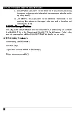
Page 16: ... not receiving link pulses on the copper interface and is therefore not correctlyattached 2 9 6OtherManagedFeatures The CityLIGHT SNMP Module also monitors the PSUs and cooling fans of both the CityLIGHT 1U or 3U Chassis and CityLIGHT 2 Card Chassis Refer to the usermanualsuppliedwiththeCityLIGHT SNMPModuleformoredetails 2 10 Shipping Contents Theshippingcartoncontains Thismanual 1 CityLIGHT 10 10...

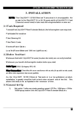
Page 17: ...0nmLightSource 3 2 Before You Start MakesurethatbothCityLIGHT chassis localandremote arecorrectlyinstalled Makesureyouhavethefollowinginformationbeforeyoustart CableType 100ΩCategory5RJ45 Fiber Connection Check that the connections on the units the patch cords used andthesiterequirementarecompatible As the CityLIGHT 10 100 Ethernet Transceiver is a long distance product installation is greatly sim...

Page 18: ...wsthe link connection to operate correctly when present the SNMP card controls this automatically With no SNMP card in either chassis one cardmusthaveswitch3 set to OFF Local and the other far end device setto ON Remote 4 If link loss forwarding is required set switch 4 to ON In this mode failuresonthefiberlinkcausethecopper user linktobedropped If the state of the fiber link is not to affect the ...

Page 19: ...12 If the Alarm LED on the CityLIGHT 10 100 Ethernet Transceiver in the remote chassis remains illuminated check that the receive power is greaterthan 28 dBm If it is less than 28 dBm check the launch power of the CityLIGHT 10 100 Ethernet Transceiver in the CityLIGHT managedchassis 13 AtbothCityLIGHT FiberExtender Modulesinsertthecopperinterfacein theRJ4510T 100TXport Toconnect to a DCE use a str...

Page 20: ...CITYLIGHT 10 100 ETHERNET TRANSCEIVER CARD 20 The hardware installation is now complete To enable management refer to the Management Serial Interface section of the CityLIGHT SNMP Module user manual ...

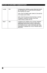
Page 21: ...EDTOTHECHASSISANDTHAT THECARDISFULLYINSERTEDINTOTHECHASSIS LINK GREEN THISINDICATESTHATTHEINTEGRITYOFTHECOPPER LINKISGOOD IFTHISLEDISNOTLIT ITMAYBEBECAUSETHE COPPERLINKISNOTINSERTED THECORRECTCABLETYPEISNOTBEINGUSED THE SUPPLIEDCROSSOVERISREQUIREDTOCONNECTTO ADTE STATION SWITCHTYPEDEVICE LINKLOSSFORWARDINGISENABLEDANDTHEFIBER LINKISINACTIVE CHECKTHESTATEOFTHEALARM LED DATA GREEN THISINDICATESTHATR...

Page 22: ...THATTHEFIBERSARECORRECTLYINSERTED TXTORXANDVICEVERSA CHECKTHATTHELINKLOSSISLESSTHAN18 dBFOR STANDARD POWEROPTICSANDLESSTHAN 25dBFORHIGH POWEROPTICS REMF RED THISINDICATESTHEREISAFAULTINTHETRANSMIT FIBERPATHFROMTHISCITYLIGHTCARDTOTHE REMOTERECEIVECITYLIGHTCARD THERECEIVE PATHFIBERISINTACT CHECKTHEFIBERLINKFROM THISCARD STRANSMITTERTOTHEFAR ENDCARD S RECEIVER ...

Page 23: ...10 100 ETHERNET TRANSCEIVER CARD 23 5 SWITCH POSITIONS Optical Link Interface Electrical User Interface ON Auto neg Link Loss Forwarding Speed 3 4 Backplane Connector 1 2 ON Local Remote Figure 3 Switch Positions ...

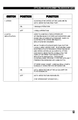
Page 24: ...ATIONISDISABLED NB AUTO NEGOTIATIONTAKESPLACEATTHE LOCALCARDCOPPERPORT THEFAR ENDCARD MUSTNEGOTIATETHESAMEOPERATINGMODE ANDSPEEDASTHELOCALCARD E G IFTHIS CARDAUTO NEGOTIATES100MbpsFDX THE CARDATTHEREMOTESITEMUSTAUTO NEGOTIATE100MbpsFDX THISWILLBE CONTROLLEDBYTHEPORTTYPETHECITYLIGHT FIBEREXTENDERMODULESCONNECTTO IFTHEREISANYDOUBT CONFIGUREALLPORTS MANUALLYUSINGFIXEDCONFIGURATION ON AUTO NEGOTIATION...

Page 25: ...SISTHEDEFAULT SETTING OFF LOCAL ONEENDOFTHELINK 3 LOCAL REMOTE ON REMOTE OTHERENDOFALINK 4 LINKLOSS FORWARDING CONTROLSWHETHERORNOTFAILURESONTHE FIBERLINKCAUSETHEUSER COPPER PORTTO BEDISABLED THISISUSEFULFORINDICATING THEFIBERFAILURETOTHEATTACHEDDEVICE WHENTHISFEATUREISDISABLED SWITCHOFF THECOPPERANDFIBERPORTSESTABLISH THEIRLINKSINDEPENDENTLY ON ENABLED OFF DISABLED ...

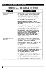
Page 26: ...PENDENTLY CONSEQUENTLYTHEDEVICES ATTACHEDTOTHECITYLIGHTFIBEREXTENDER MODULESMUSTHAVETHESAMEHIGHEST OPERATINGMODE IFINDOUBT CONFIGUREALL DEVICESTOHAVEAFIXEDOPERATINGMODE TYPICALLY100MbpsFDX THELINKLEDDOESNOT ILLUMINATE THECITYLIGHT10 100ETHERNETTRANSCEIVER CANNOTDETECTTHECONNECTEDDEVICE CHECK THECONNECTEDDEVICEISTURNEDON CABLEINCORRECTLYINSTALLED CHECKTHATTHE CABLEISCORRECTLYINSERTEDINTHERJ45 CONNE...

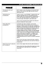
Page 27: ... CHECKTHE RECEIVECONNECTORSANDMAKESUREPOWERIS CORRECTLYSUPPLIEDTOALLDEVICES THERECEIVE POWERLIGHTLEVELSHOULDBEGREATERTHAN 28 dBm IFTHERECEIVEPOWERISLESSTHAN 28dBmAT THECITYLIGHT1UOR3UCHASSIS CHECKTHE LAUNCHPOWEROFTHECITYLIGHT10 100ETHERNET TRANSCEIVERINTHEREMOTECHASSISISGREATER THAN 10dBmFORTHESTANDARD POWERUNITAND 3 dBmFORTHEHIGH POWERUNIT IFTHERECEIVE POWERISLESSTHAN 28dBm CHECKTHELAUNCH POWEROF...

Page 28: ...SINDEPENDENTLYAND THEREFOREMUSTBECONNECTEDTODEVICESTHAT TRADEUP TOTHESAMESPEED NOTE THEACTIVITYLEDWILLONLYILLUMINATEWHEN DATAISBEINGTRANSMITTEDOVERTHELINK If aftergoingthroughthetroubleshootingsection youfailtoresolveyourproblem andrequiremorehelp pleasecontactBlackBox TechnicalSupportat724 746 5500 withthefollowinginformation 1 Unittype 2 Unitserialnumber 3 Environmentlay out Includehubs bridgesa...

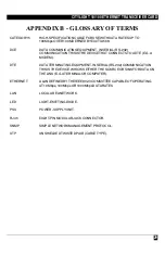
Page 29: ...HATCONNECTSTOADTE E G A MODEM DTE DATATERMINATINGEQUIPMENT INSERIAL RS 232 COMMUNICATION THISISTHEDEVICEWHICHISEITHERTHESOURCEORSINKFORDATAON THELINK E G ATERMINALORCOMPUTER ETHERNET ALANDEFINEDBYTHEIEEE802 3COMMITTEECAPABLEOFOPERATING AT10Mbps 100MbpsOR1000MbpsDATARATES LAN LOCALAREANETWORK LED LIGHT EMITTINGDIODE PSU POWER SUPPLYUNIT RJ45 EIGHT PINMODULARJACKCONNECTOR SNMP SIMPLENETWORKMANAGEMEN...

Page 30: ... Copyright2000 BlackBoxCorporation Allrightsreserved 1000 Park Drive Lawrence PA 15055 1018 724 746 5500 Fax 724 746 0746 ...

Reviews: