


724-746-5500 | blackbox.com
21
ServSwitch Universal Extender
21
6. Troubleshooting
We recommend that all products be assembled, configured and tested prior to the final
installation to eliminate the possibility of problems on site.
Make sure all connections to the PC and peripheral equipment are solid. Reboot the PC if any
of the connections were loose because this may have caused the PC to lock up.
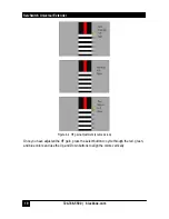
If the problem is related to video, check the function and calibration by placing the unit in
Calibration mode using the switch on the sender unit. If the image on the display is not
centered properly, use the LCD’s on screen display to do an Auto Adjust Image.
If you cannot troubleshoot the setup, note all pertinent symptoms and make a list of any other
equipment used in the setup.
WARNING: The units contain hazardous voltages. There are no user-serviceable parts inside.
Do not open or try to repair the unit yourself. There is no customer-repairable item in the unit,
and you will void the warranty. Contact Black Box Technical Support at 724-746-5500 or
[email protected].
If there is a problem with USB devices, check the state of the LED’s on the front panel of the
each unit. These LED’s pertain to USB links. The General purpose USB (STD) link light
should be on if proper connection is made between the sender and the receiver units. The
Data LED lights if connection to PC is made and a device is plugged into one of the STD USB
ports on the receiver unit. The DR1 and DR2 LEDs function when the sender unit is
connected to the PC and the receiver unit at the remote end is connected to a USB device
(such as a printer). Link and data LEDs work together. If connection to the PC of DR1 or DR2
is verified, but the Link and Data LEDs are off, unplug the corresponding device from the
receiver unit, wait five seconds and plug it back in.
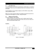
Check the RJ-45 port connections (A to A, B to B, etc.) to make sure they are not crossed,
loose, or disconnected. Use the following list to narrow your search depending on device you
are having trouble with
•
Port A of the UTP carries VGA A and AUDIO signals
•
Port B of the UTP carries VGA B and Bi-directional RS232 signals
•
Port C of the UTP carries the Standard (STD) USB and the “Direct” USB port DR1.
•
Port D of the UTP carries the “Direct” USB port DR2


